9
4
CONTROL VALVE
DISASSEMBLY AND ASSEMBLY
4J0AX00CONTROL VALVE
Disassembly
For disassembly of the control valve, follow the procedure
below. For assembly of the control valve, follow the same
procedure as for disassembly in the reverse order.
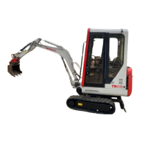
Valve assembly
1. Loosen the nuts (1) and remove the tie rods (2), then
remove the sections.
Be sure to apply position marks to each section to
avoid mistakes during assembly.
Nut (1): 26.5 to 29.4 N·m (19.5 to 21.7 ft-lb.)
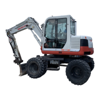
2. Remove the O-ring.
• Thecontactsurfaceisofametalseal.Payattention
not to damage or make a dent on it.
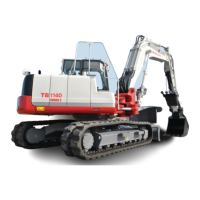
3. Remove the main relief valve and the port relief valve,
and then remove the O-ring from the relief valve.
• Donotdisassembleunlessnecessary.Thepressure
value set in the valve is changed if the lock nut is
loosened and the setscrew is turned.
• Donotfurtherdisassembletheportreliefvalveasit
is impossible to adjust pressure after reassembly.
Main relief valve: 74 ±5 N·m (54.6 ±3.7 ft-lb.)
Port relief valve: 74 ±5 N·m (54.6 ±3.7 ft-lb.)
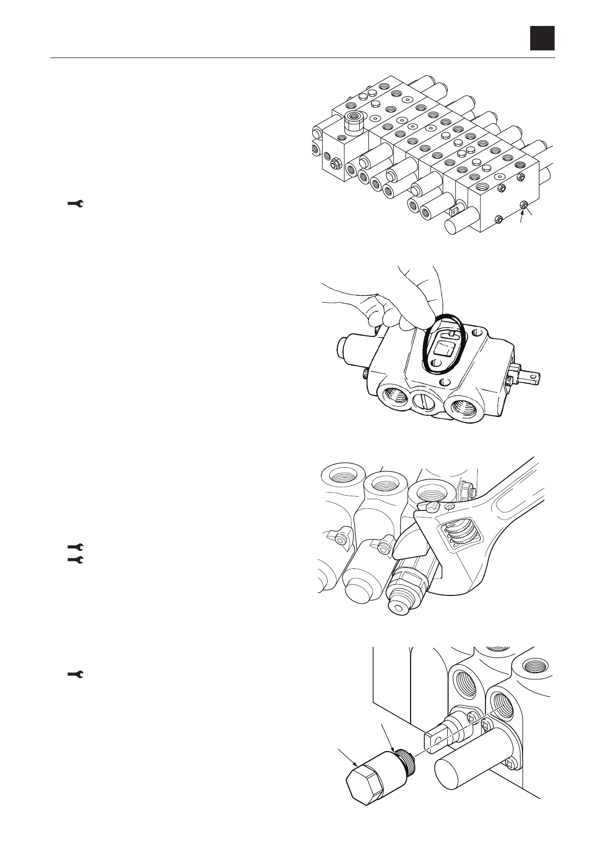
4. Remove the anti-cavitation valve (1), and then remove
the O-ring from the anti-cavitation valve.
Anti-cavitation valve: 74 ±5 N·m (54.6 ±3.7 ft-lb.)
 Loading...