FUNCTION
SLEW MOTOR
2
3
SLEW MOTOR 3N0AX00
Hydraulic motor 2
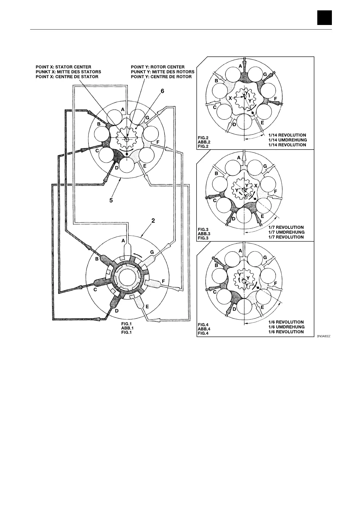
Figure 1 shows that the rotor (6) rotates in the direction of the arrow while making contact with the inside of the stator
(5) when the high-pressure oil is directed into the chambers B, C and D. This in turn causes the valve (2) to rotate,
which causes the chambers into which the high-pressure oil is directed to be successively shifted in the direction op-
posite the direction of the arrow. Figure 2 shows that the rotor (6) has turned 1/14 of a revolution, resulting in the cham-
bers into which the high-pressure is to be directed to be shifted to the chambers A, G and F. At this time, the center
point Y of the rotor (6) is shifted to the point Y’ around the point X. This point Y’ is further shifted to Y” as shown in Figure
3. In other words, the center of the rotor (6) rotates 6/7 of a revolution around the point X, changing its position from Y
to Y’ and then to Y”. Figure 4 shows that the center of the rotor is returned to point Y from point Y’’ to complete one cycle
of the shifting of the chambers into which the high-pressure oil is to be directed.
At this time, the “•” mark on the rotor (6) rotates 1/6 of a revolution in the direction opposite that of the motion of point Y.
As a result, the output shaft is made to rotate one complete rotation by the high-pressure oil, which is directed into 42
chambers, which is 7 chambers × 6 cycles = 42 chambers.
 Loading...