SERVICE DATA
HYDRAULIC CIRCUIT DIAGRAM
3
2
HYDRAULIC CIRCUIT DIAGRAM 2F0AX001
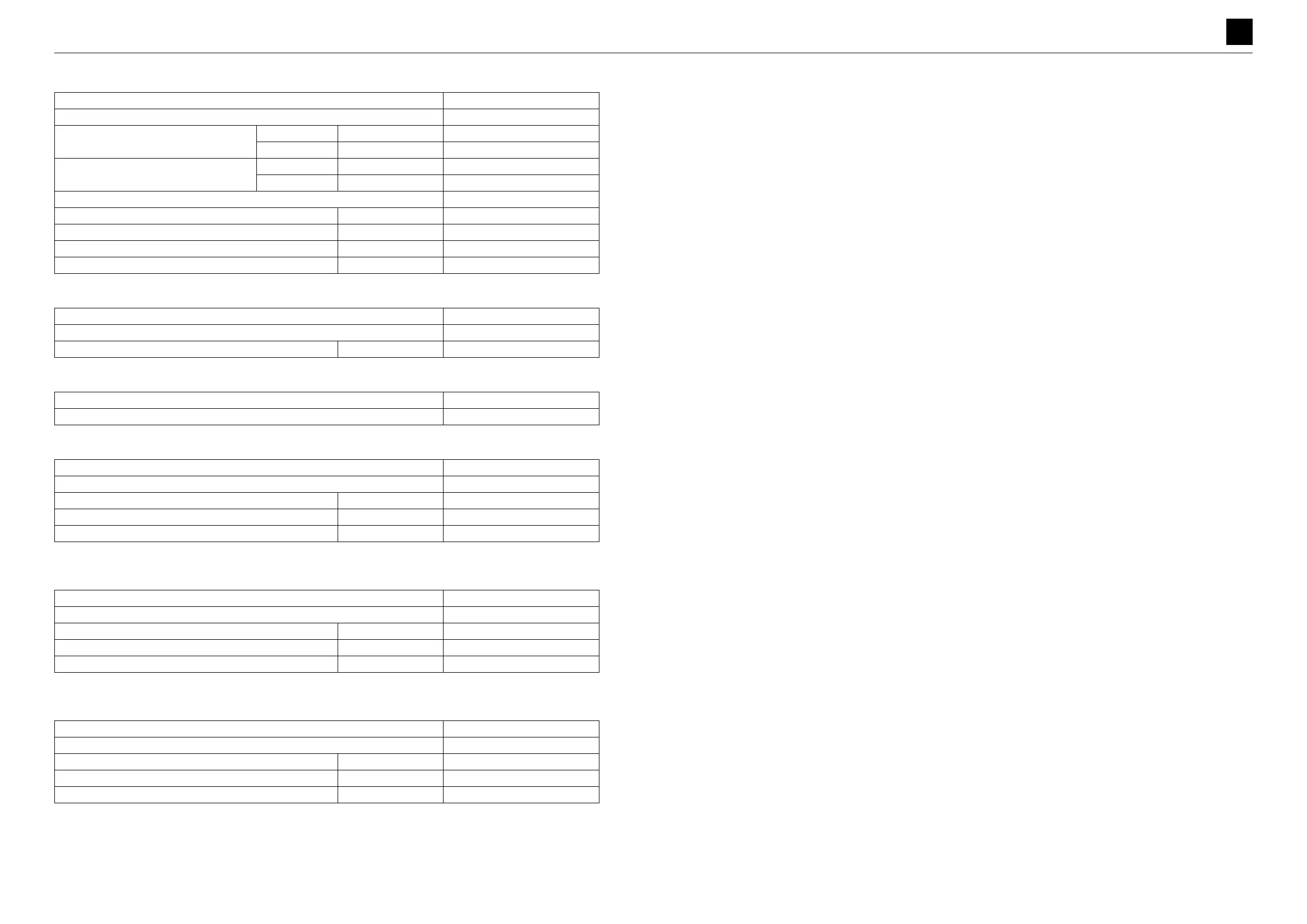
Travel motor
Solenoid valve (Lever lock and travel speed switching)
Swivel joint
Boom cylinder
* Length from the center of the pinhole on the tube side to the center of the pinhole on the rod side
Arm cylinder
* Length from the center of the pinhole on the tube side to the center of the pinhole on the rod side
Bucket cylinder
* Length from the center of the pinhole on the tube side to the center of the pinhole on the rod side
Part number 19031-30300
Type PHV-1B-12B-PT
Total displacement
1st cm
3
/rev (cu. in./rev) 421.3 (25.7)
2nd cm
3
/rev (cu. in./rev) 232 (14.2)
Motor displacement
1st cm
3
/rev (cu. in./rev) 11.4 (0.7)
2nd cm
3
/rev (cu. in./rev) 5.8 (0.3)
Reduction gear ratio 1/36.96
2nd-speed switching speed MPa (psi) 3.4 (493)
Parking brake torque N·m (ft.-lb.) 22.6 (16.7)
Parking brake release pressure MPa (psi) 1.9 (116)
Amount of reduction gear lubricant used L (US gal.) 0.33 (0.35)
Part number 19017-62800
Type AGCH-16826
Power supply voltage V 12
Part number 19040-07600
Type YV-7151A
Part number 19001-16100
Type –
Bore diameter × rod diameter mm (in.) 60×35 (2.4×1.4)
Stroke mm (in.) 480 (18.9)
Maximum retraction length* mm (in.) –
Part number 19001-16200
Type –
Bore diameter × rod diameter mm (in.) 60×35 (2.4×1.4)
Stroke mm (in.) 385 (15.2)
Maximum retraction length* mm (in.) –
Part number 19001-13700
Type –
Bore diameter × rod diameter mm (in.) 50×30 (2.0×1.2)
Stroke mm (in.) 355 (14.0)
Maximum retraction length* mm (in.) –
 Loading...