GTS Technical Manual
5. March 2013 Edition: V1.10/2013 5-43
Copyright © 2013, Diversey Inc.
05.64.10 tool lowering unit - foot lever - 455B_755B eco_V1.00.fm
5.8 Tool lowering unit
5.8.1 Removing of foot lever
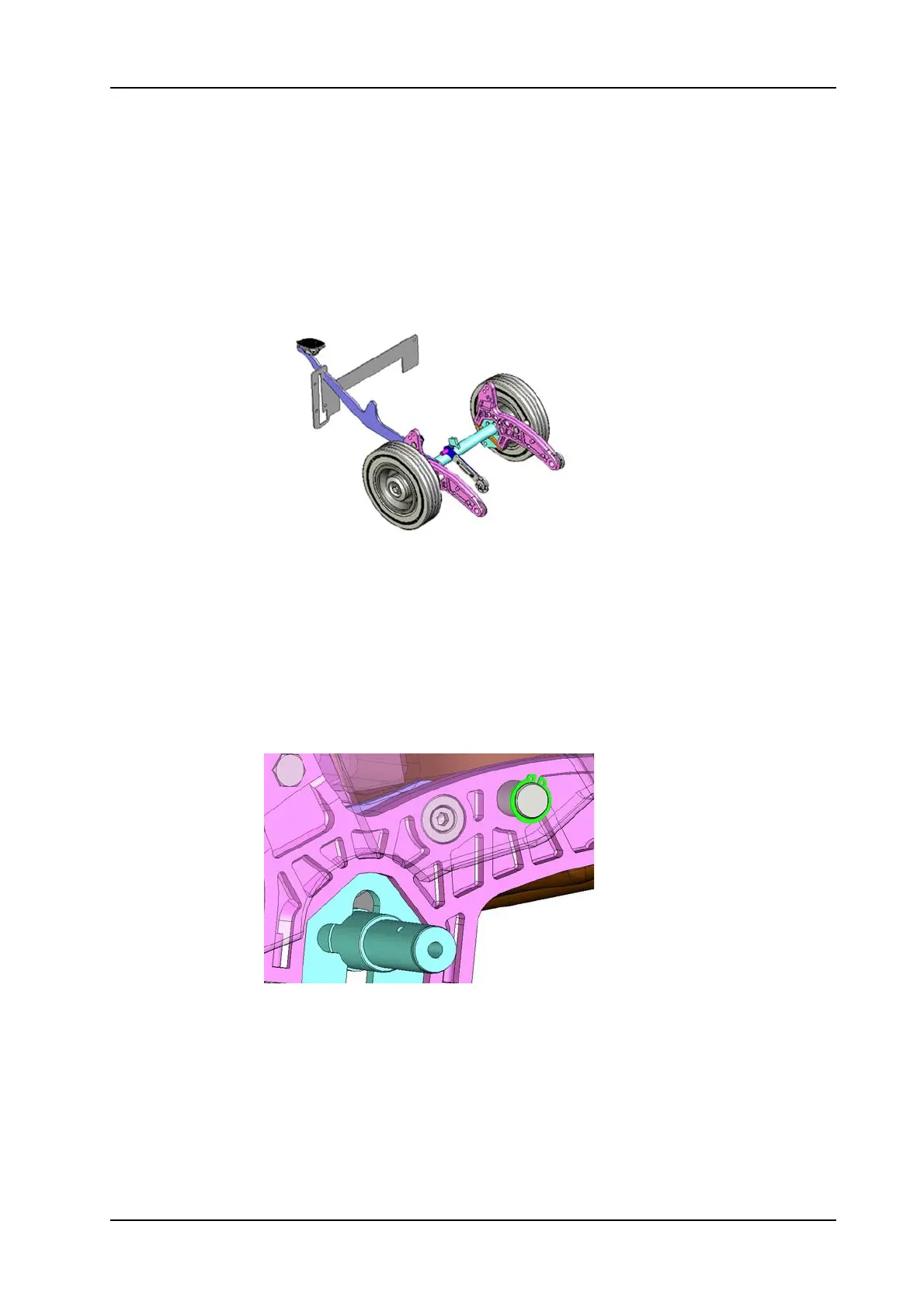
Picture 64: Tool lowering unit
• Lay the machine to the LH side.
• Remove the pressure spring (455B:07/143, 755B:06/112)
• Unplug microswitch.
• Unscrew microswitch fixation screw (455B:06/117, 755B:07/
117).
• Remove microswitch (455B:06/123, 755B:07/123).
• Remove wheel (455B:07/142, 755B:06/109) on RH side.
• Remove retaining ring (455B:06/107, 755B:07/107).
Picture 65: Tool lowering pin detail
• Remove axle (455B:06/112, 755B:07/112) on RH side.
• Pull the cradle out so you can reach the counter screw (455B:06/
127, 755B:07/127).
• Remove two nuts (455B:06/113, 755B:07/113) and (455B:06/
126, 755B:07/126) and washer (455B:06/105, 755B:07/105).
• Remove the foot lever (455B:06/104, 755B:07/104).
 Loading...