GTS Technical Manual
5. March 2013 Edition: V1.10/2013 5-44
Copyright © 2013, Diversey Inc.
05.64.10 tool lowering unit - foot lever - 455B_755B eco_V1.00.fm
5.8 Tool lowering unit
5.8.2 Mounting of foot lever
Picture 66: Tool lowering screws detail
• Build in new foot lever.
• Position washer and nuts, then tighten them.
• Position cradle and foot lever in the correct position.
• Assemble axle.
• Assemble microswitch and adjust accordingly.
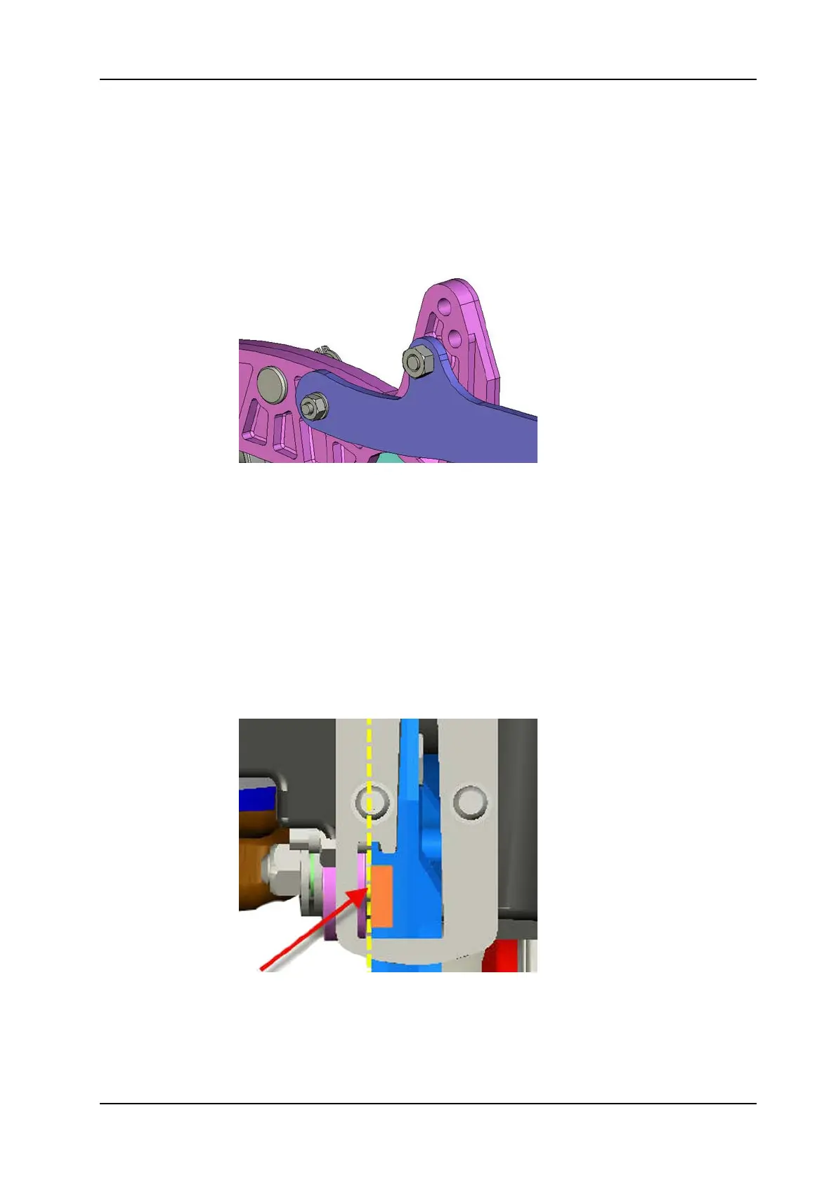
Adjustment
The foot lever switch has to apply when the foot lever passes the
centre of the LH side of the stop plate squeegee (455B:06/102,
755B:07/102).
Picture 67: Tool lowering switching point
• Mount the wheel.
• Connect microswitch.
• Position pressure spring.
• Lift up machine.
 Loading...