5
ROUTINE MAINTENANCE
Air Sensor Calibration (Air Mode)
5-24 TP04300 Series Interface & Applications Manual
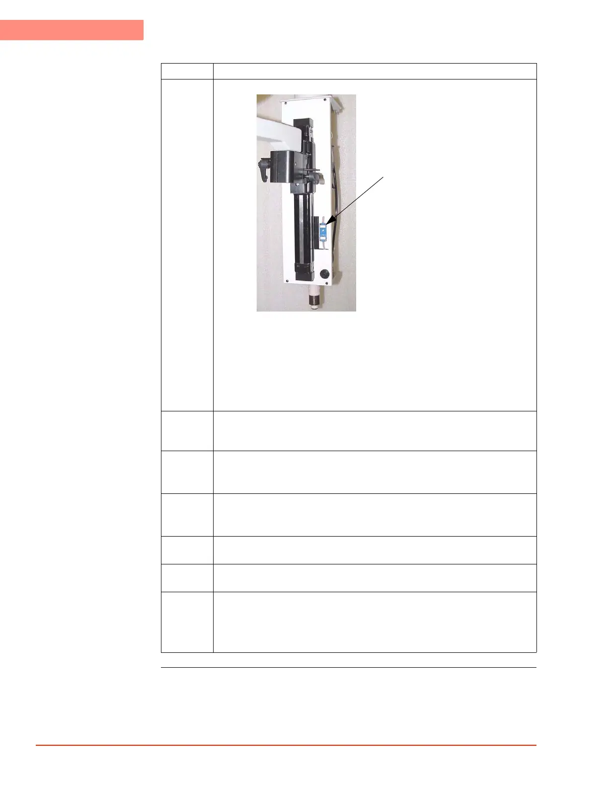
4 Disconnect the calibration jack (blue) on the rear of the Thermal Head.
Plug a male connector from the Calibrator into the female connector of the
Calibration Jack.
Take care to observe plug pin polarity.
DO NOT use the male connector of the Calibration Jack.
NOTE: because the internal head assembly is NOT easily accessible on 4300B
Systems, the thermocouple from the calibrator must be interfaced directly with
the Watlow Board (J5).
5 Press the Utilities Screen tab, then press the "Sensor Calibration" button to
display the Calibration Select Sensor Screen, then press "Air’ to display
Calibrate Air Screen.
6 Follow the on-screen prompts to set the Low Temperature Calibration Point.
Set Calibrator output to -60.0 °C, then press "Next" to display Calibrate Low
Temperature (Air) Screen. Allow graph plot to stabilize at low temperature.
7 Follow the on-screen prompts to set the High Temperature Calibration Point.
Set Calibrator output to +200.0 °C, then press "Next" to display Calibrate High
Temperature (Air) Screen. Allow graph plot to stabilize at high temperature.
8 Press "Next" to display Calibration Done (Air) Screen, then press "Done" to
return to Utilities Screen.
9 Optional: use Calibrator to set new setpoint: see if System runs to the Calibrator
setpoint.
10 Disconnect the Calibrator from the Calibration Jack.
Re-connect the male and female ends of the Calibration Jack.
Take care to observe plug pin polarity.
Reinstall the sensor access cover.
Step Action
Calibration Jack

 Loading...