. . . . .
PREPARATION FOR USE
Sensor Interface Guidelines
TP04300 Series Interface & Applications Manual 2-33
Sensor Interface Guidelines
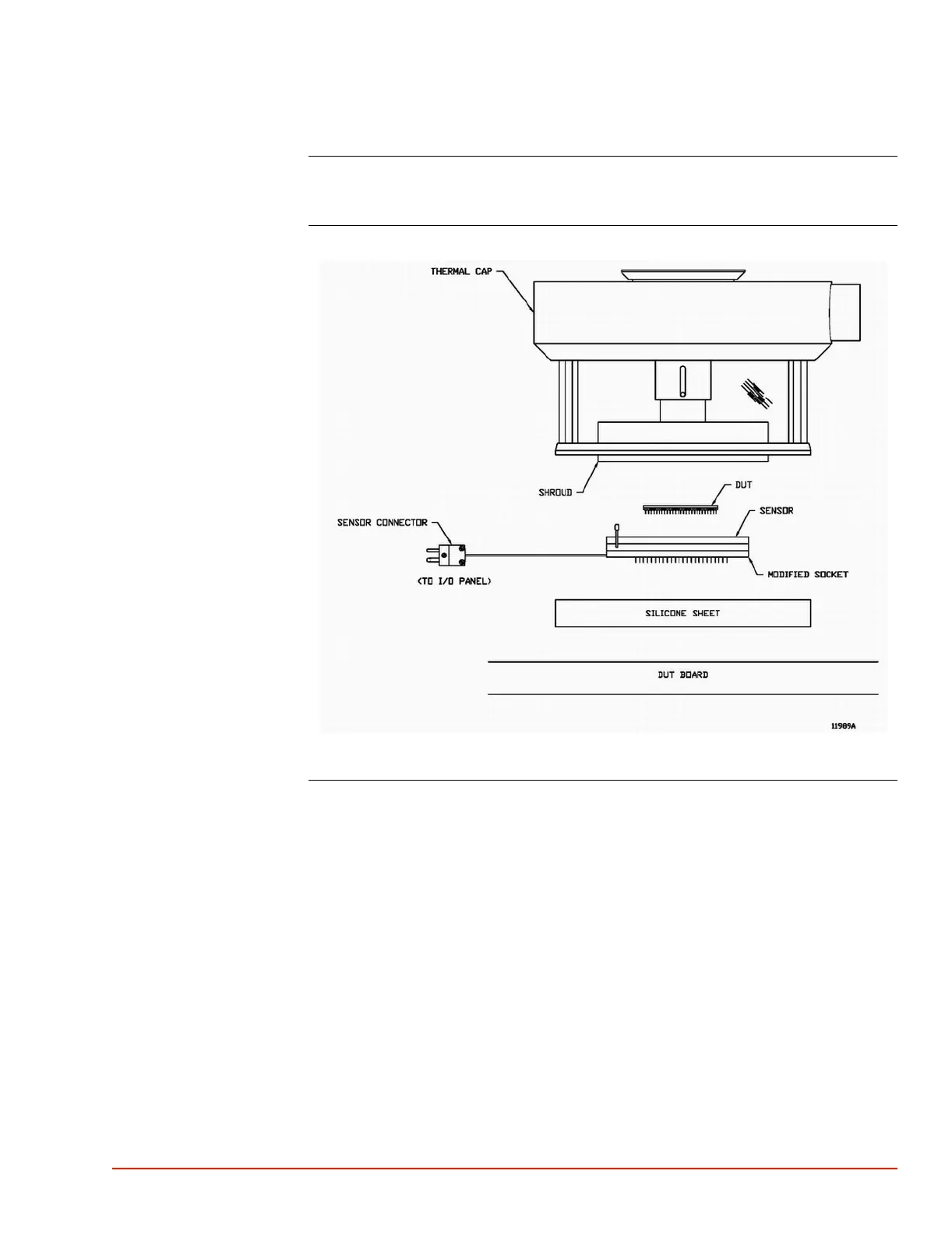
Introduction The System permits the DUT to be placed within the temperature control loop (see illustration
below) by accepting input from an external thermocouple or external RTD temperature sensor.
DUT Test Fixture
Interface
11989IA.jpg
Interfacing
Guidelines
Follow these sensor interfacing guidelines:
1. All materials used in fixturing should be capable of withstanding the total system speci-
fied temperature range as listed in the System Specification.
2. The DUT sensor must be located within the test fixture, be in contact with the DUT, and
be properly connected to the appropriate Input/Output port. When installing the thermo-
couple plug at the System I/O Panel port, take care to observe thermocouple connector
polarity.
3. The sensor should be durable, be of low mass to retard thermal conductivity, have reason-
able surface contact area, and be mounted such that it is thermally isolated from the socket
to eliminate heat sinking.
4. The fixturing should ensure repeatable contact with the DUT.
5. The tested device body should not contact the socket body.
6. Do not ground the sensor: if the DUT case is grounded, then isolate the sensor by using
a material which is electrically nonconductive but is an excellent thermal conductor.

 Loading...