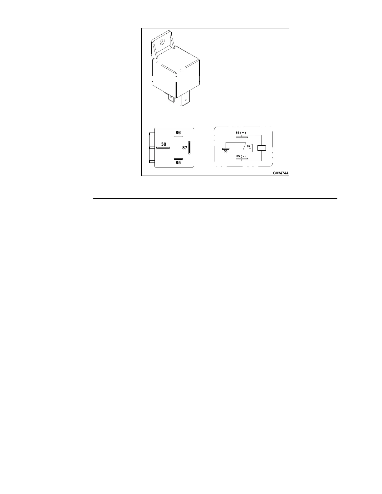
TestingtheRelayswith4Terminals
g034744
Figure227
1.Parkthemachineonalevelsurface,lowerthecuttingdeck,shutoffthe
engine,settheparkingbrake,andremovethekeyfromthekeyswitch.
2.Toensurethatthemachineoperationdoesnotoccurunexpectedly,
disconnectthenegative(-)cablefromthebatteryandthendisconnectthe
positive(+)cablefromthebattery;refertoServicingtheBattery(page5–110).
3.Locatetherelaythatistobetested.
4.Disconnectthewireharnesselectricalconnectorfromtherelay.
Note:Beforetakingthesmallresistancereadingswithadigitalmultimeter,
shortthemultimetertestleadstogether.Themeterdisplaysasmall
resistancevalue(usually0.5ohmsorless).Thisresistanceisbecauseofthe
internalresistanceofthemultimeterandtestleads.Subtractthisvaluefrom
themeasuredvalueofthecomponentthatyouaretesting.
5.Checkthecoilresistancebetweentheterminals85and86withamultimeter
(ohmssetting).Theresistancemustbeapproximately72ohms.
6.Connectthemultimeter(ohmssetting)leadstotherelayterminals30and
87.Thengroundterminal85andapply+12VDCtoterminal86.Therelay
mustbreakthecontinuitybetweentheterminals30and87as+12VDCis
setandremovedfromterminal86.
7.Disconnectthevoltageandleadsfromtherelayterminals.
8.Replacetherelayiftestingdeterminesthatitisdamaged.
9.Connectthewireharnesselectricalconnectortotherelayafteryoucomplete
thetesting.
10.Connectthepositive(+)cabletothebatteryandthenconnectthenegative
(-)cabletothebattery;refertoServicingtheBattery(page5–110).
ElectricalSystem:TestingtheElectricalComponents
Page5–86
Groundsmaster360
16225SLRevC

 Loading...