Micro-Master Touch User Guide
64
© 2014 Toro Australia Pty Ltd Ver 1.2, June 2014
11 Pump Sets
11.1 Overview and Operation
The Micro-Master Touch controller supports up to eight pump sets. Each individual pump set can
consist of up to four pumps. Each of the four pumps can allocated to any station output in the
controller. Each pump set can be enabled or disabled. Additionally, each of the four pumps can be
individually enabled or disabled, have a priority assigned, and a pump capacity. If installed, a pump
set can be allocated a flow meter. Each program, or single station program can use one of the pump
sets.
Pump Set Operation
When a program or single station program starts, the assigned pump set is also started. If a pump on
delay is set, the pumps are delayed by the set time. Depending on the parameters for the pump set,
one or more of the pumps will start.
If no flow meter is allocated, all allocated pumps will start at the same time, or with a delay set by the
inter pump delay setting.
If a flow meter is allocated, further pumps will be started or stopped as required based on the flow
rate from the flow meter.
If the VFD pump setting is ticked, pump 1 will always be the first pump started. If the runtime
levelling setting is ticked, the next pump to be started will be pump with the lowest total run time. If
the runtime levelling setting is not ticked, the next pump to start is determined by the pump priority. If
any pump priorities are the same, the first pump in numerical order is started. The VFD setting has
precedence over runtime levelling, which has precedence of the pump priority.
When the flow rate reduces sufficiently, pumps will be turned off in the reverse order in which they
were turned on. When a program stops, and a pump off delay is set, the pump set will continue to
run for the set time. At the end of the pump off delay, any running pumps are stopped. If an inter
pump delay is set, the pumps are turned off using the inter pump delay.
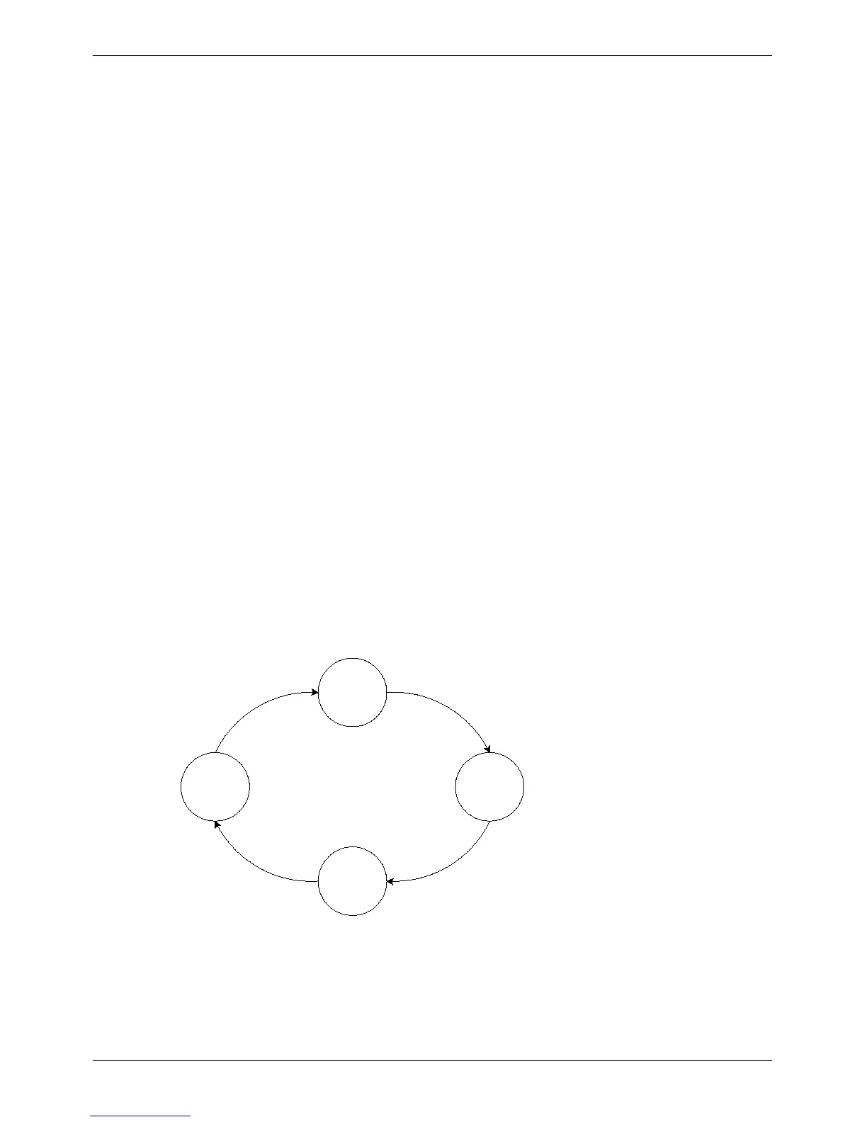
The pump set operation is shown in Figure 42.
Idle
DelayOn
Active
DelayOff
Program
Start
Delay
Complete
Program
Stop
Delay
Complete
Figure 42 - Pump Set Operation Schematic
 Loading...