8-32 Phaser 6125/6130 Color Laser Printer Service Manual
Service Parts Disassembly
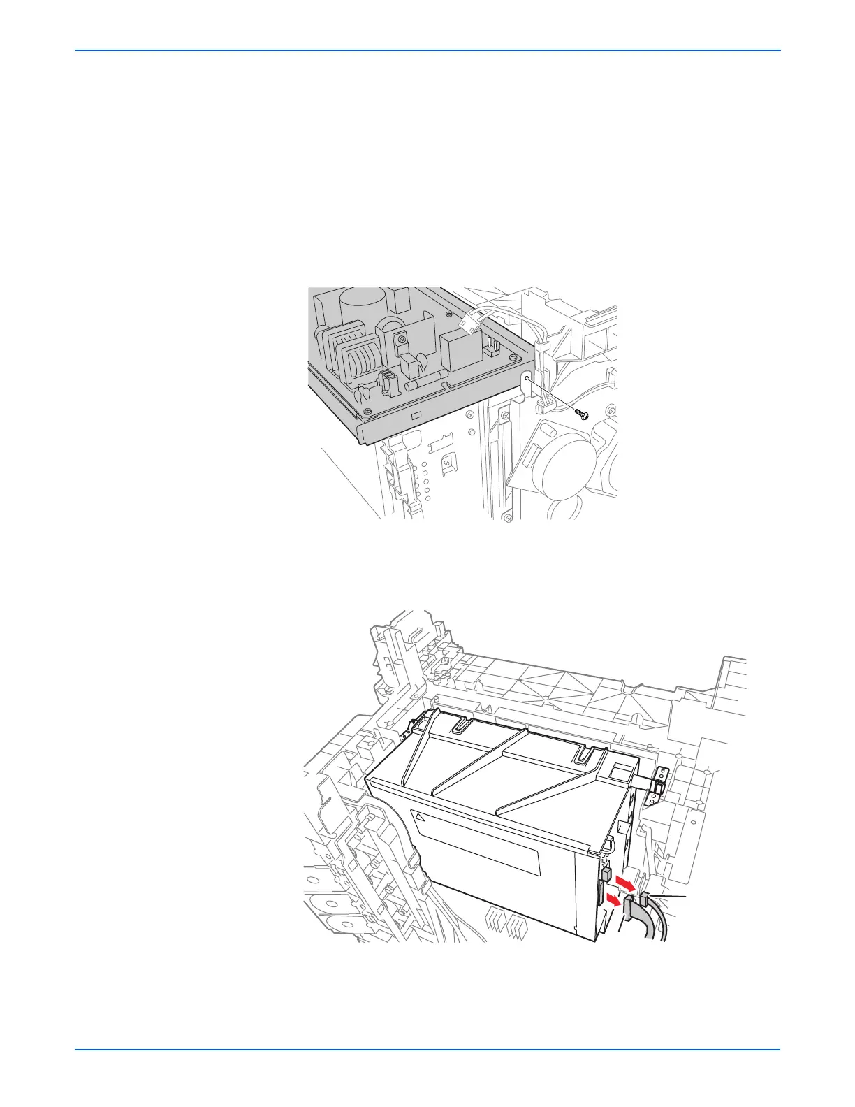
6. Remove the two screws (silver, 6mm) that attach the Right MCU Bracket
to the printer.
7. Remove the Right MCU Bracket from the printer.
8. Remove all the connectors on the LVPS Board. Release the Fuser
Harness from the Fuser Harness Guide.
9. Release the latches of the Fuser Harness Guide and slide it to the left to
release the hooks from the LVPS Frame.
10. Remove the two screws (silver, 6mm) and the six screws (silver, tap,
8mm) that attach the LVPS Frame to the printer.
11. Remove the screw (silver, M4, 6mm) that attaches the Sub-Drive to the
LVPS Frame, remove the LVPS Frame from the printer together with the
LVPS Board.
12. Remove the four screws (silver, tap 8mm) that attach the left and right
sides of the Laser Unit Springs to the printer. Remove the Laser Unit
Springs from the printer.
13. Unplug the two connectors (P/J411, 412) from the Laser Unit.
s6130-095
 Loading...