10-6 Phaser 6125/6130 Color Laser Printer Service Manual
Plug/Jack and Wiring Diagrams
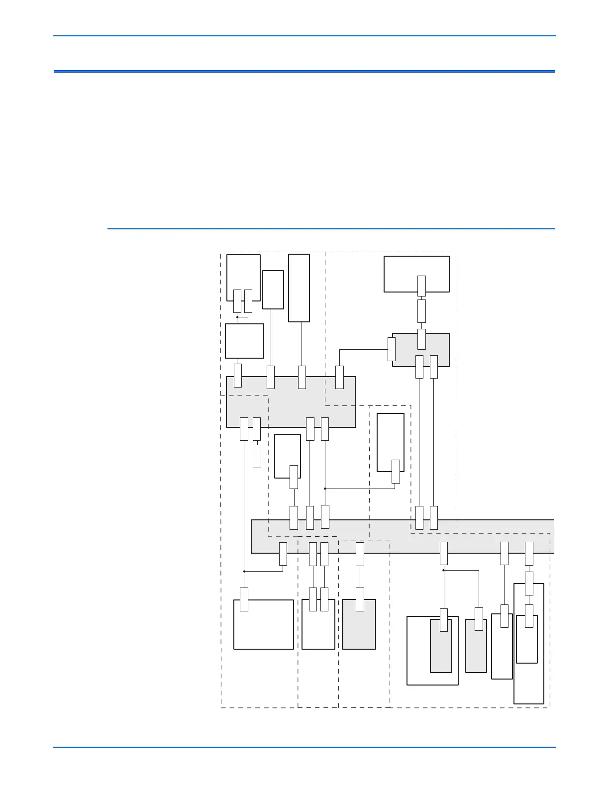
Plug/Jack Locators
Maps 1 through 4 indicate the location of key connections within the printer.
Connections are referenced by their P/J designation.
1. General Diagram - Plug/Jack Locations
2. Map 1 - Transfer Unit, Control Panel, Imaging Unit, Dispenser, Fuser
3. Map 2 - Laser Unit, Feeder Assembly
4. Map 3 - LVPS, Drive Motors, I/P Board, AC Power
5. Map 4 - Toner Dispenser Motors, HVPS, MCU
General Diagram - Plug/Jack Locations
MCU Board
PL8.2.13
HVPS
PL4.1.19
P/J16
P161
Humidity Sensor
PL8.2.7
P/J20
P/J42
P/J201
ADC Sensor
P/J281P/J2811
EEPROM
P/J28
EEPROM
PL8.2.16
P/J144
P/J422
Erase LEDs
PL4.1.8
P/J141
Print Cartridge
PL4.1.21
Transfer
Assembly
PL6.1.7
P/J47
LVPS
PL8.2.1
P/J40
IP Board
PL8.1.7
Control
Panel
PL1.1.18
P/J101
P/J111
P/J29
P/J401
P/J10
P/J11
P/J220
P/J2900
8 Fuser
4 Laser
6 High Voltage
5 Xerographic
P/J17
P/J171
P/J48
GFI
Breaker
PL8.2.11
P/J483
P/J482
Fan
PL8.1.1
Interlock Harness
PL8.2.5
Switch
PL5.1.9
P/J503
P/J44
P/J15
P/J502
P/J14
P/J501
P/J29 P/J291
Power
Switch
Harness
PL8.2.9
Laser
PL4.1.1
Fuser
PL6.1.1
P/J412 P/J41
P/J411 P/J40
s6130-057
P/J504
Used In Production
Process Only.
J5041
1 DC Power Supply
9 Controller
 Loading...