7 Series FPGAs GTP Transceivers User Guide www.xilinx.com 149
UG482 (v1.9) December 19, 2016
RX Fabric Clock Output Control
Table 4-18 defines the attributes required for RX fabric clock output control.
Using RXRATE
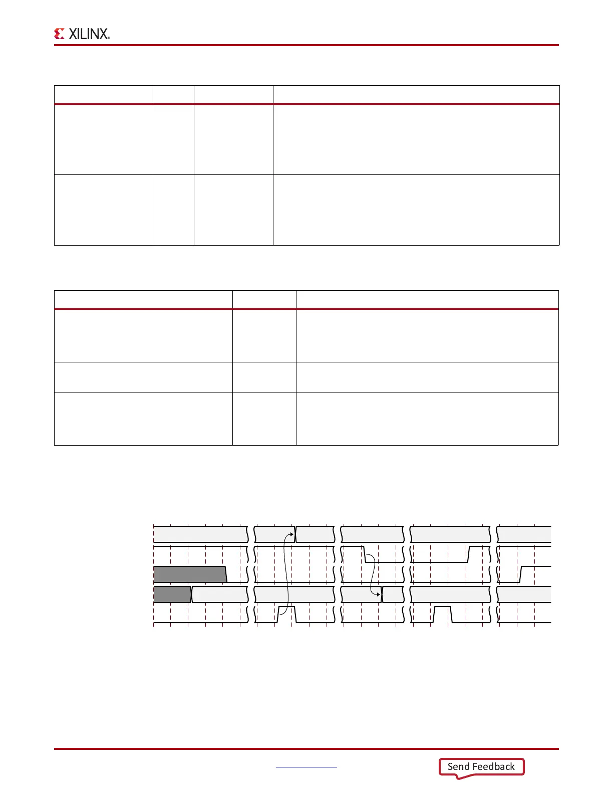
When users want to change the divider D setting via RXRATE, the steps in Figure 4-19 should be
performed:
Notes relevant to Figure 4-19:
1. DRP wr denotes the function of performing a DRP write to Addr 9'h011. The exact DRP
transaction is not shown.
RXRATEMODE In Async Determines if RXRATE should be treated as synchronous or
asynchronous.
0: Synchronous. When set to 1'b0, an automatic reset sequence
occurs in response to a change on the RXRATE port.
1: Asynchronous.
RXDLYBYPASS In Async RX delay alignment bypass:
0: Uses the RX delay alignment circuit. Set to 1'b0 when the RX
buffer is bypassed.
1: Bypasses the RX delay alignment circuit. Set to 1‘b1 when the RX
buffer is used.
Table 4-17: RX Fabric Clock Output Control Ports (Cont’d)
Port Dir Clock Domain Description
Table 4-18: RX Fabric Clock Output Control Attributes
Attribute Type Description
TRANS_TIME_RATE 8-bit Hex Reserved. The recommended value from the 7 Series FPGAs
Transceivers Wizard should be used. This attribute determines
when PHYSTATUS and RXRATEDONE are asserted after a rate
change.
RXBUF_RESET_ON_RATE_CHANGE String When set to TRUE, this attribute enables automatic RX buffer reset
during a rate change event initiated by a change in RXRATE.
RXOUT_DIV Integer This attribute controls the setting for the RX serial clock divider.
This attribute is only valid when RXRATE = 3'b000. Otherwise
the D divider value is controlled by RXRATE. Valid settings are 1,
2, 4, and 8.
X-Ref Target - Figure 4-19
Figure 4-19: RXRATE change example
UG482_c4_119_020713
RXRATE
RXPMARESETDONE
RXRATEDONE
DRP wr (addr ’h011, bit[11])
DRPRDY
div m div n
1’b0 restore setting

 Loading...


