156 www.xilinx.com 7 Series FPGAs GTP Transceivers User Guide
UG482 (v1.9) December 19, 2016
Chapter 4: Receiver
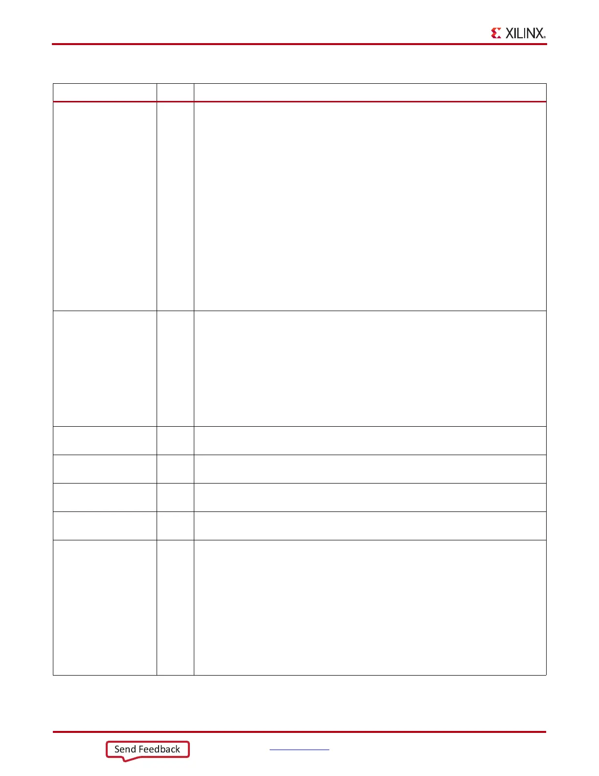
ES_CONTROL 6-bit
Binary
[0]: RUN.
Asserting this bit causes a state transition from the WAIT state to the RESET state,
initiating a BER measurement sequence.
[1]: ARM
Asserting this bit causes a state transition from the WAIT state to the RESET state,
initiating a diagnostic sequence. In the ARMED state, deasserting this bit causes a state
transition to the READ state if one of the states of bits [5:2] below is not met.
[5:2]:
0001 In the ARMED state, causes a trigger event (transition to the READ state) when an
error is detected (i.e., an unmasked 1 on the Sdata bus).
0010 In the ARMED state, causes a trigger event (transition to the READ state) when the
qualifier pattern is detected in Rdata.
0100 In the ARMED state, causes a trigger event (transition to the READ state) when the
eye_scan_trigger port asserts High.
1000 In the ARMED state, causes a trigger event (transition to the READ state)
immediately.
es_control_status 4-bit
Binary
[0]: DONE. Asserted High only in the WAIT, END, or READ states.
[3:1]: Current state of the state machine:
WAIT 000
RESET 001
COUN 011
END 010
ARMED 101
READ 100
es_rdata 80-bit
Binary
When a trigger event occurs in the ARMED state, es_rdata[39:0] is the present state of the Rdata
bus and es_rdata[79:40] is the previous state of the Rdata bus.
es_sdata 80-bit
Binary
When a trigger event occurs in the ARMED state, es_sdata[39:0] is the present state of the Sdata
bus and es_sdata[79:40] is the previous state of the Sdata bus.
es_error_count 16-bit
Hex
In END and WAIT states, contains the final error count for the preceding BER measurement.
es_sample_count 16-bit
Hex
In END and WAIT states, contains the final sample count for the preceding BER measurement.
RX_DATA_WIDTH Integer Sets the bit width of the RXDATA port. When 8B/10B encoding is enabled, RX_DATA_WIDTH
must be set to 20 or 40. Valid settings are 16, 20, 32, or 40.
See Interface Width Configuration, page 214 for more details.
Width of valid data on Rdata and Sdata buses is the width of the internal datapath (16-bit or 20-bit).
For the different possible bus widths, the previous and current valid Rdata and Sdata bits
correspond to the following indices in ES_SDATA_MASK, ES_QUALIFIER,
ES_QUAL_MASK, es_rdata, and es_sdata:
valid Rdata and Sdata width previous data current data
16 [79:64] [39:24]
20 [79:60] [39:20]
Table 4-20: RX Margin Analysis Attributes (Cont’d)
Attribute Type Description