Wiring with the logic relay
98
1SVC 440 795 M0100
Analog value comparator/
threshold value switch
The logic relay provides 16 analog comparators A1 to A16
for use as required. These can also be used as threshold
value switches or comparators.
An analog value comparator or threshold value switch
enables you to compare analog input values with a setpoint,
the actual value of another function relay or another analog
input. This enables you to implement small controller tasks
such as two-point controllers very easily.
All CL-AC1, CL-AC2 and CL-DC2 devices are provided with
analog inputs.
• The analog inputs of the CL-LSR/CL-LST are I7 and I8.
• The analog inputs of the CL-LMR/CL-LMT are I7, I8, I11
and I12
The following comparisons are possible:
h
Compatibility with AC010 devices
If you have loaded an existing AC010 circuit diagram, the
previous comparator functions and values are retained.
The analog comparator function relay operates in CL-LSR/
CL-LST and CL-LMR/CL-LMT as well as in AC010 devices.
The setpoints are converted to the new resolution of the
analog inputs. The setpoint 5.0 (AC010) produces the
setpoint 512 (CL-LSR/CL-LST, CL-LMR/CL-LMT).
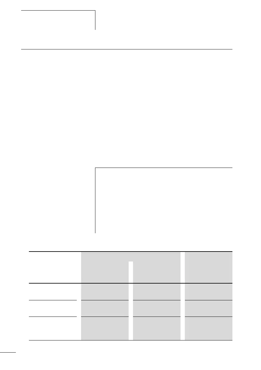
Value at function
relay input I11
Comparator functions Value at function
relay value input
I2
Mode selection at
the function relay
Analog input I7, I8,
I11, I12
Analog input I7, I8,
I11, I12
Setpoint 0000 to
9999
Setpoint 0000 to
9999
Actual value of
counter relay C1 to
C16
Actual value of
counter relay C1 to
C16
 Loading...


