Appendix
258
1SVC 440 795 M0100
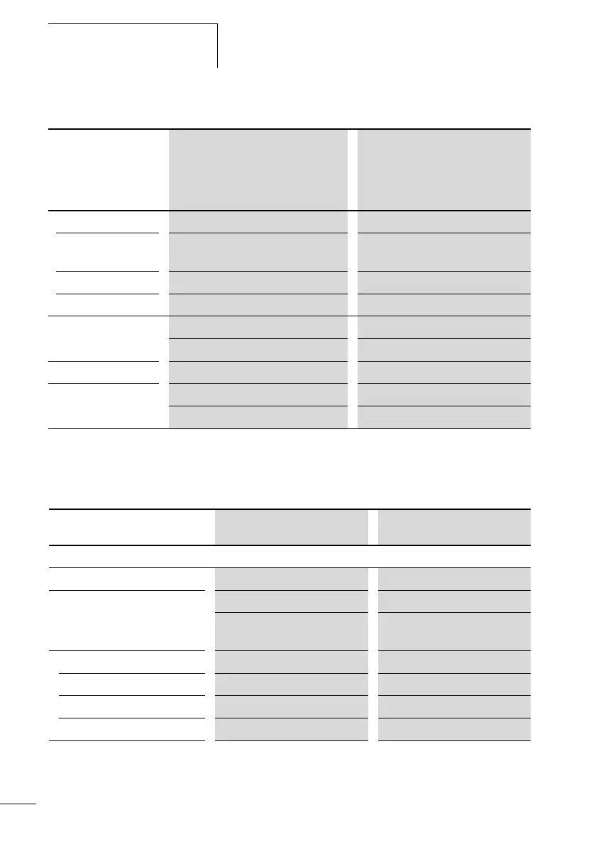
CL-LSR...DC1, CL-LMR...DC1, CL-LS...DC2, CL-LM...DC2
Inputs
CL- LSR...AC1, CL-LMR...AC1
CL-LSR...DC1,
CL-LMR...DC1
CL-LSR...DC2,
CL-ST...DC2,
CL-LMR...DC2,
CL-LMT...-DC2
Rated voltage
Nominal value 12 V DC,
+30 %, –15 %
24 V DC, +20 %, –15 %
Permissible range 10.2 to 15.6 V DC 20.4 to 28.8 V DC
Residual ripple 5 % 5 %
Input current
at rated voltage
CL-LSR...DC1 CL-LMR...DC1 CL-LS...DC2 CL-LM...DC2
Normally 140 mA Normally 200 mA Normally 80 mA Normally 140 mA
Voltage dips 10 ms, IEC/EN 61 131-2 10 ms, IEC/EN 61 131-2
Power loss CL-LS...DC1 CL-LM...DC1 CL-LS...DC2 CL-LM...DC2
Normally 2 W Normally 3.5 W Normally 2 W Normally 3.5 W
CL- LSR...AC1 CL-LMR...AC1
Digital inputs 24 V AC
Quantity 8 12
Status display LCD (if provided) LCD (if provided)
2 inputs (I7, I8) usable as
analog inputs
4 inputs (I7, I8, I11, I12) usable
as analog inputs
Potential isolation
To power supply No No
Between each other No No
To the outputs Yes Yes
 Loading...


