Technical data
267
1SVC 440 795 M0100
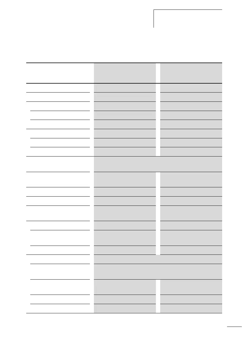
Transistor outputs
CL-LST, CL-LMT, CL-LET.20DC2
CL-LST CL-LMT,
CL-LET.20DC2
Number of outputs 4 8
Contacts Semiconductors Semiconductors
Rated voltage U
e
24 V DC 24 V DC
Permissible range 20.4 to 28.8 V DC 20.4 to 28.8 V DC
Residual ripple F 5 % F 5 %
Supply current
At state ”0” Normally 9 mA, max. 16 mA Normally 18 mA, max. 32 mA
At state ”1” Normally 12 mA, max. 22 mA Normally 24 mA, max. 44 mA
Reverse polarity protection Yes, Attention! If voltage is applied to the outputs when the polarity
of the power supply is reversed, this will result in a short circuit.
Potential isolation to mains
supply, inputs
Yes Yes
Rated current I
e
on 1 signal max. 0.5 A DC max. 0.5 A DC
Lamp load 5 Watts without R
V
5 Watts without R
V
Residual current on 0 state
per channel
< 0,1 mA < 0,1 mA
Max. output voltage
On 0 state
with ext. load 10 M
2.5 V 2.5 V
On 1 state, Ie = 0.5 A U = U
e
– 1 V U = U
e
– 1 V
Short-circuit protection Yes, thermal (analysis via diagnostics input I16, I15; R16, R15)
Short-circuit tripping current
for Ra F 10 mO
0,7 A F I
e
F 2 A per output
Max. total short-circuit
current
8 A 16 A
Peak short-circuit current 16 A 32 A
Thermal cutout Yes Yes
 Loading...


