247
1SVC 440 795 M0100
7 What happens if …?
You may sometimes find that the logic relay does not do
exactly what you expect. If this happens, read through the
following notes which are intended to help you solve some
of the problems you may encounter.
You can use the power flow display in the logic relay to
check the logic operations in the CL circuit diagram with
reference to the switching states of contacts and relays.
Only qualified persons should test the logic relay voltages
while the device is in operation.
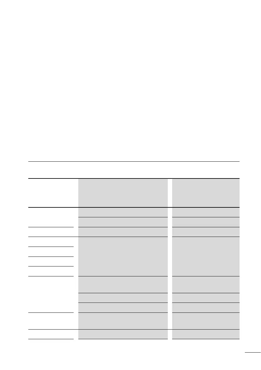
Messages from the
CL system
Messages from
the CL system on
the LCD display
Explanation Remedy
No display Power supply interrupted Switch on the power supply
LCD is faulty Replace logic relay
Continuous display
TEST: AC Self-test aborted Replace logic relay
TEST: EEPROM
TEST: DISPLAY
TEST: CLOCK
ERROR: I2C Memory module removed or not inserted
correctly before saving
Insert memory module
Memory module is faulty Change memory module
Logic relay is faulty Replace logic relay
ERROR: EEPROM The memory for storing the retentive values
or the CL circuit diagram memory is faulty.
Replace logic relay
ERROR: CLOCK Clock error Replace logic relay
 Loading...


