227
1SVC 440 795 M0100
6 Inside the logic relay
Logic relay
circuit diagram cycle
In conventional control systems, a relay or contactor control
processes all the rungs in parallel. The speed with which a
contactor switches in this case depends on the components
used, and ranges from 15 to 40 ms for relay pick-up and
drop-out.
With the circuit diagram the logic relay is processed with a
microprocessor that simulates the contacts and relays of the
circuit concerned and thus processes all switching
operations considerably faster. Depending on its size, the CL
circuit diagram is processed cyclically every 2 to 40 ms.
During this time, the logic relay passes through five
segments in succession.
How the logic relay evaluates the circuit diagram:
In the first three segments the logic relay evaluates the
contact fields in succession. The logic relay checks whether
contacts are switched in parallel or in series and saves the
switching states of all contact fields.
In the fourth segment, the logic relay assigns the new
switching states to all the coils in one pass.
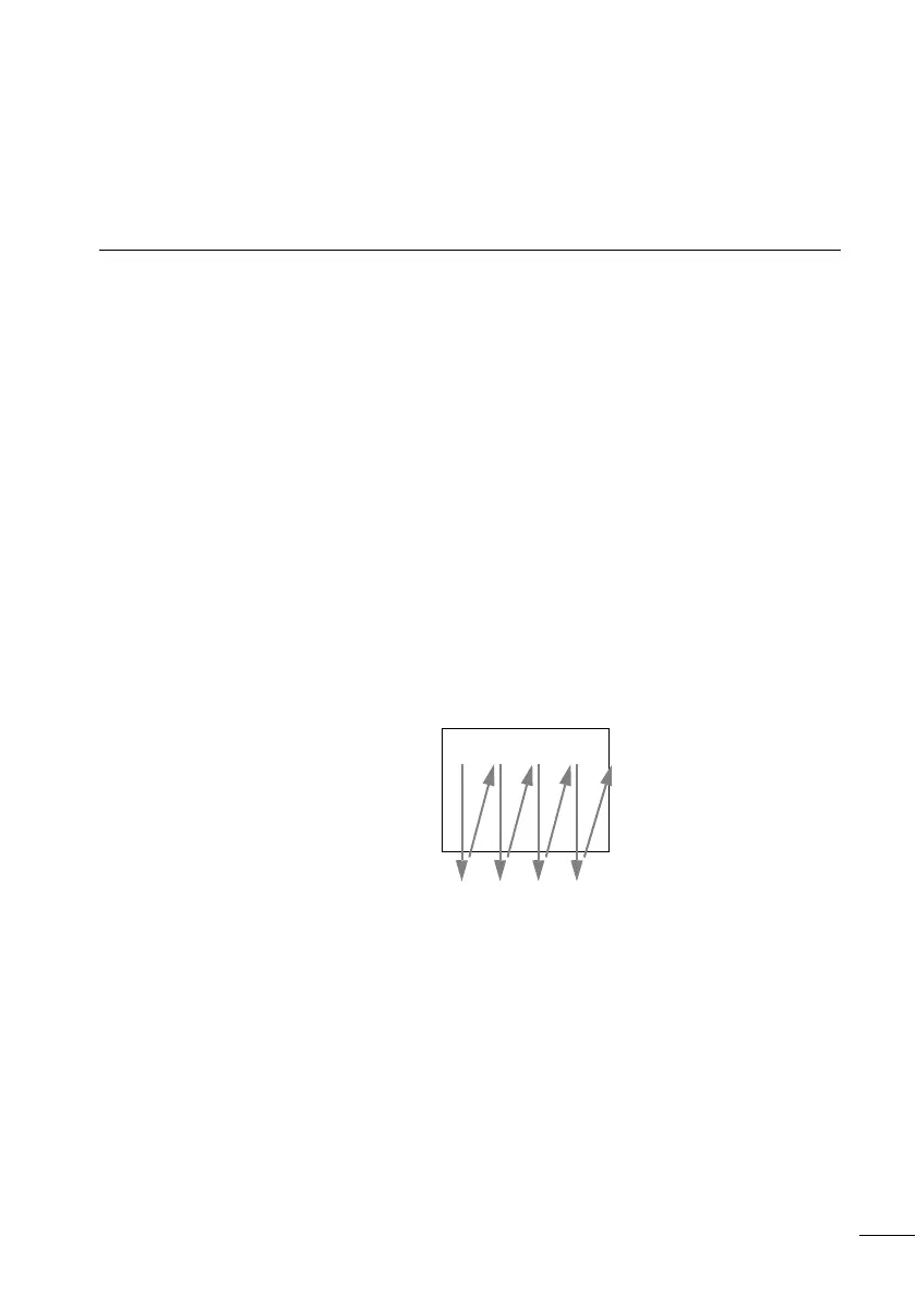
Rungs Segment
123 45
1
2
3
4
…
I1-q1-j--ÄQ8
I1-I4-Ö1-TT2
I2-I3----RT2
T2-u-----ÄQ1
P1-kêê êêê
 Loading...


