Working with contacts and
relays
77
1SVC 440 795 M0100
Completed circuit diagrams are transferred between your PC
and the logic relay via the connecting cable. Once you have
transferred a circuit diagram, simply run the logic relay
straight from your PC.
Details on the program and transferring circuit diagrams are
given in section “CL-SOFT”, Page 243.
Working with contacts
and relays
In CL circuit diagrams, the switches, buttons and relays of
conventional circuit diagrams are connected up using input
contacts and relay coils.
Input and output contacts
First specify which input and output terminals you wish to
use in your circuit.
Depending on the type and configuration, the logic relay has
8, 12 or 24 input terminals and 4, 6, 8, 10 or 16 outputs. The
signal states on the input terminals are detected in the circuit
diagram with the input contacts I1 to I12. R1 to R12 are the
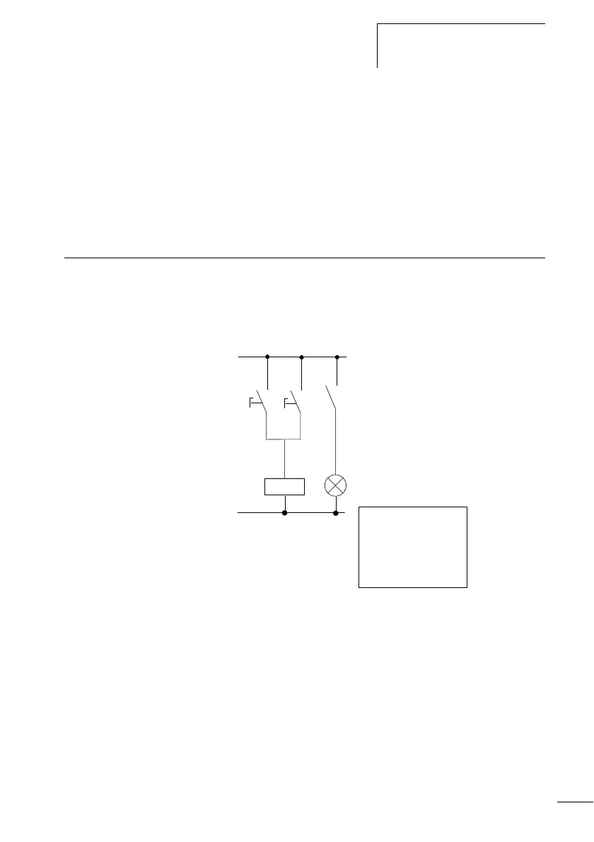
Conventional circuit Wired with the logic relay
CL connection
Connect n/o contact S1 to
input terminal I2
Connect n/o contact S2 to
input terminal I3
Connect load H1 to the device output Q4
S1 or S2 switch on H1.
CL circuit diagram
H1
S1
K1
K1
S2
I2u------ÄQ4
I3k
 Loading...


