Inside the logic relay
240
1SVC 440 795 M0100
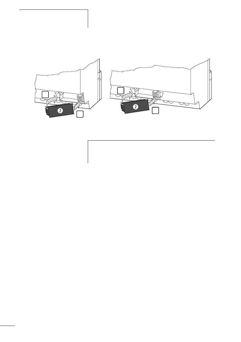
Figure 89: Insert memory module
Loading or saving circuit diagrams
You can only transfer circuit diagrams in STOP mode.
Behaviour of CL device without integrated keypad,
display when loading the memory module
The CL modules without a keypad and LCD display transfer
the circuit diagram from the inserted memory module to
CL-LSR..X.../CL-LST..X... or CL-LMR..X.../CL-LMT..X.. when
the power supply is switched on. The circuit diagram in the
logic relay is retained if the circuit diagram on the memory
module is invalid.
Behaviour of CL device with integrated keypad,
display when memory module is inserted
If the logic relay does not contain a circuit diagram, the
circuit diagram is loaded from the memory module
automatically when the logic relay is switched on.
CL-LSR/CL-LST (CL-LAS.MD003): CL-LMR/CL-LMT (CL-LAS.MD003):
2
1
1
2
h
With the logic relay you can insert and remove the memory
module even if the power feed is switched on, without the
risk of losing data.
 Loading...


