7.2.3 Connection examples for high impedance differential
protection
WARNING! USE EXTREME CAUTION! Dangerously high
voltages might be present on this equipment, especially on the plate
with resistors. De-energize the primary object protected with this
equipment before connecting or disconnecting wiring or performing
any maintenance. The plate with resistors should be provided with a
protective cover, mounted in a separate box or in a locked cubicle.
National law and standards shall be followed.
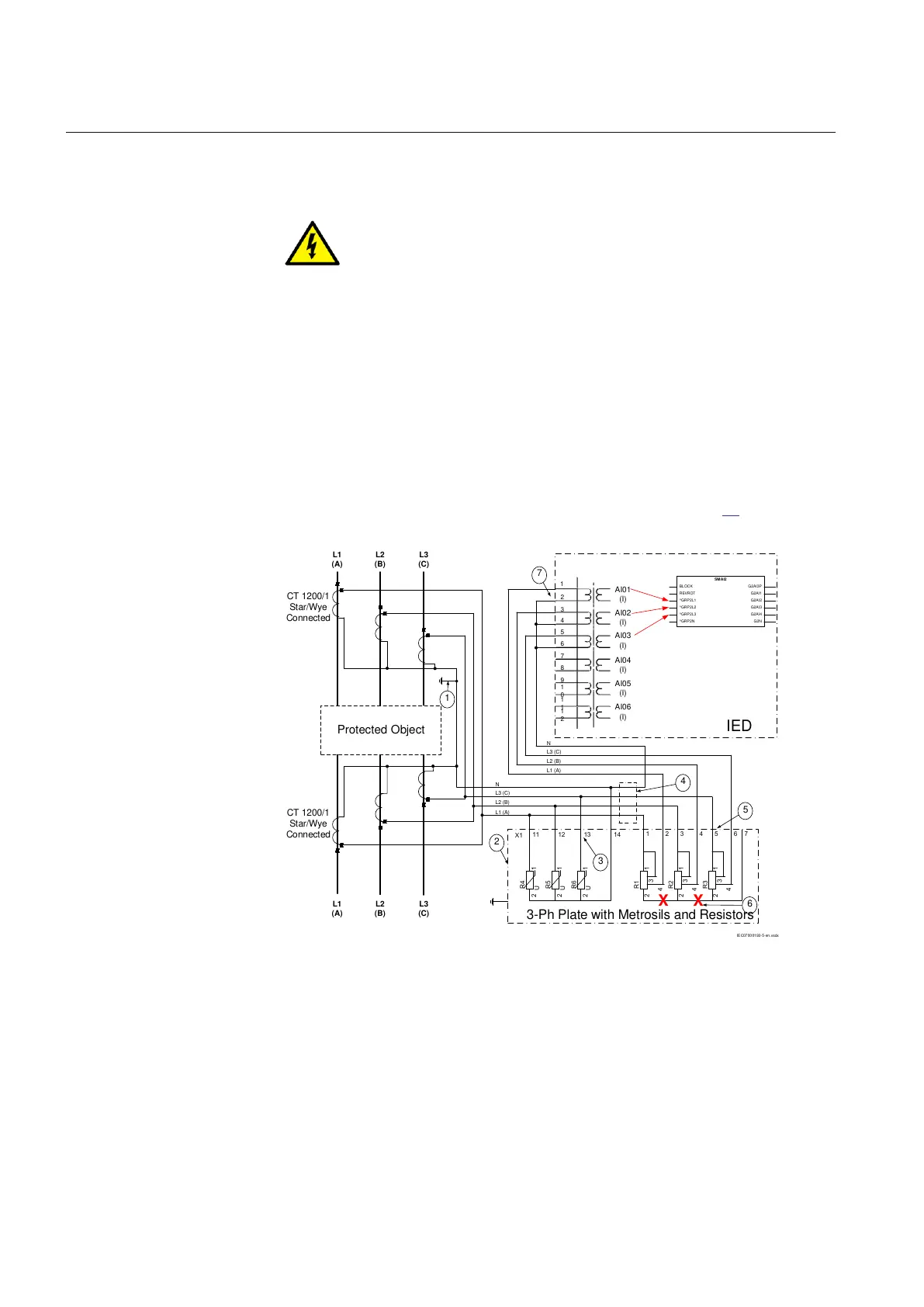
7.2.3.1 Connections for three-phase high impedance differential protection
Generator, reactor or busbar differential protection is a typical application for three-
phase high impedance differential protection. Typical CT connections for three-phase
high impedance differential protection scheme are shown in figure 61.
L1
(A)
L2
(B)
L3
(C)
Protected Object
CT 1200/1
Star/Wye
Connected
L1
(A)
L2
(B)
L3
(C)
CT 1200/1
Star/Wye
Connected
7
8
9
1
0
1
1
1
2
1
2
3
4
5
6
AI01
(I)
AI02
(I)
AI03
(I)
AI04
(I)
AI05
(I)
AI06
(I)
7
6
X1
R4
R5
R6
1
2
1
2
1
2
11 12 13 14
U
U
U
R1
1
3
4
2
1
3
R2
2
4
1
3
R3
2
4
1 2 3 4 5 6 7
L1 (A)
L2 (B)
L3 (C)
N
3-Ph Plate with Metrosils and Resistors
2
3
5
4
X X
L1 (A)
L2 (B)
L3 (C)
N
1
IED
IEC07000193-5-en.vsdx
SMAI2
BLOCK
REVROT
^GRP2L1
^GRP2L2
^GRP2L3
^GRP2N
G2AI3P
G2AI1
G2AI2
G2AI3
G2AI4
G2N
IEC07000193 V5 EN
Figure 61: CT connections for high impedance differential protection
Section 7 1MRK 502 071-UEN -
Differential protection
156 Generator protection REG670 2.2 IEC and Injection equipment REX060, REX061, REX062
Application manual

 Loading...


