17.1.4.1 Setting examples
Three setting examples, in connection to Measurement function (CVMMXN), are
provided:
• Measurement function (CVMMXN) application for a OHL
• Measurement function (CVMMXN) application on the secondary side of a
transformer
• Measurement function (CVMMXN) application for a generator
For each of them detail explanation and final list of selected setting parameters values
will be provided.
The available measured values of an IED are depending on the actual
hardware (TRM) and the logic configuration made in PCM600.
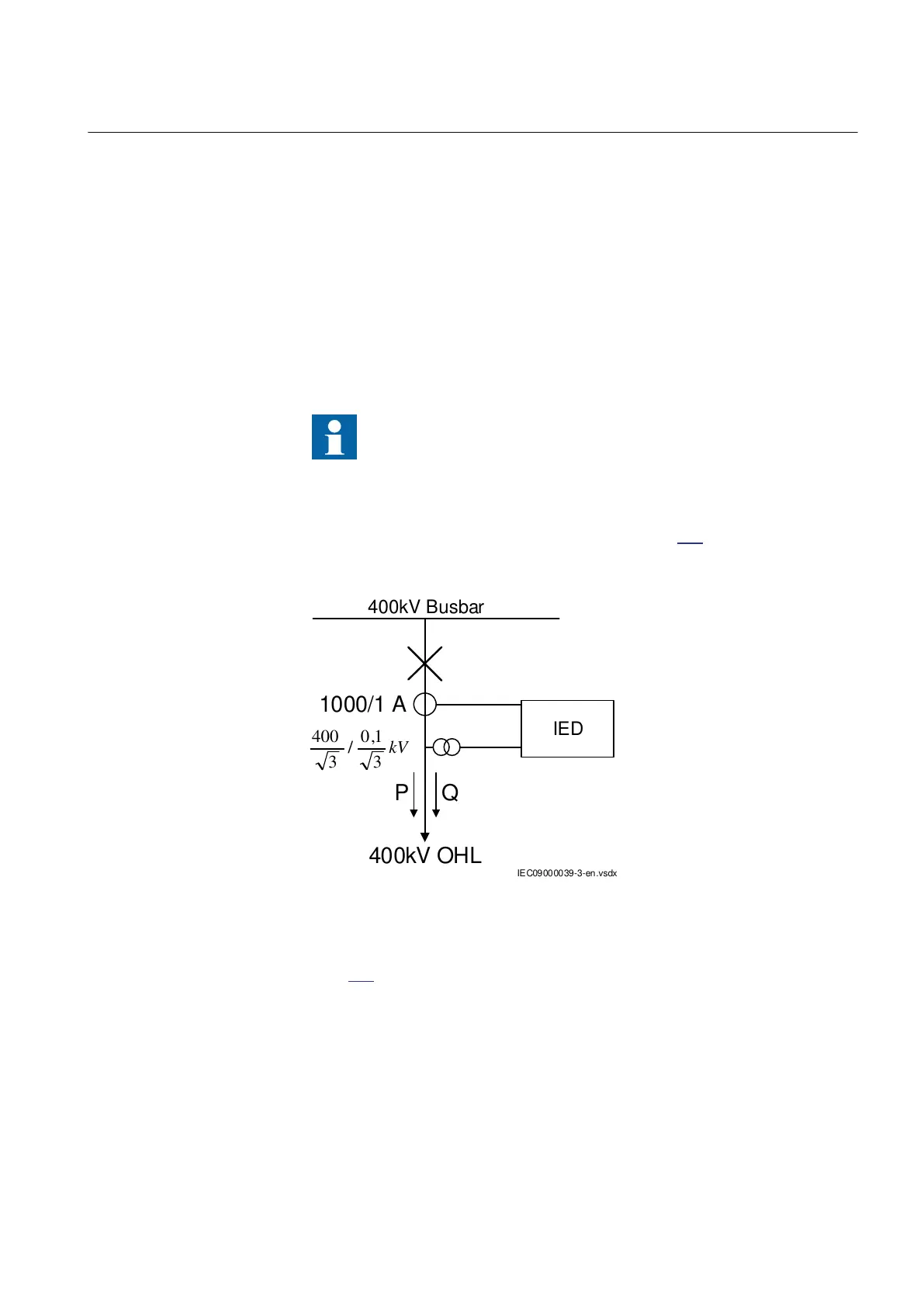
Measurement function application for a 400kV OHL
Single line diagram for this application is given in figure 309:
400kV Busbar
400kV OHL
P Q
1000/1 A
IEC09000039-3-en.vsdx
IED
IEC09000039-1-EN V3 EN
Figure 309: Single line diagram for 400kV OHL application
In order to monitor, supervise and calibrate the active and reactive power as indicated
in figure
309 it is necessary to do the following:
1. Set correctly CT and VT data and phase angle reference channel PhaseAngleRef
using PCM600 for analog input channels
2. Connect, in PCM600, measurement function to three-phase CT and VT inputs
3. Set under General settings parameters for the Measurement function:
1MRK 502 071-UEN - Section 17
Monitoring
Generator protection REG670 2.2 IEC and Injection equipment REX060, REX061, REX062 629
Application manual

 Loading...


