1 2
A
EnergizingCheck
UHighBusEnerg > 50 - 120 % of GblBaseSelBus
UHighLineEnerg > 50 - 120 % of GblBaseSelLine
ULowBusEnerg < 10 - 80 % of GblBaseSelBus
ULowLineEnerg < 10 - 80 % of GblBaseSelLine
UMaxEnerg < 50 - 180 % of GblBaseSelBus and/or
GblBaseSelLine
Line voltageBus voltage
IEC10000078-4-en.vsd
B
IEC10000078 V4 EN
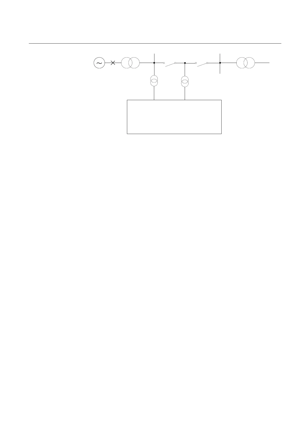
Figure 225: Principle for the energizing check function
The energizing operation can operate in the dead line live bus (DLLB) direction, dead
bus live line (DBLL) direction, or in both directions over the circuit breaker.
Energizing from different directions can be different for automatic reclosing and
manual closing of the circuit breaker. For manual closing it is also possible to allow
closing when both sides of the breaker are dead, Dead Bus Dead Line (DBDL).
The equipment is considered energized (Live) if the voltage is above the set value for
UHighBusEnerg or UHighLineEnerg of the base voltages GblBaseSelBus and
GblBaseSelLine, which are defined in the Global Base Value groups; in a similar way,
the equipment is considered non-energized (Dead) if the voltage is below the set value
for ULowBusEnerg or ULowLineEnerg of the respective Global Base Value groups.
A disconnected line can have a considerable potential due to factors such as induction
from a line running in parallel, or feeding via extinguishing capacitors in the circuit
breakers. This voltage can be as high as 50% or more of the base voltage of the line.
Normally, for breakers with single breaking elements (<330 kV) the level is well
below 30%.
When the energizing direction corresponds to the settings, the situation has to remain
constant for a certain period of time before the close signal is permitted. The purpose
of the delayed operate time is to ensure that the dead side remains de-energized and
that the condition is not due to temporary interference.
15.1.2.4 Voltage selection
The voltage selection function is used for the connection of appropriate voltages to the
synchrocheck, synchronizing and energizing check functions. For example, when the
IED is used in a double bus arrangement, the voltage that should be selected depends
on the status of the breakers and/or disconnectors. By checking the status of the
disconnectors auxiliary contacts, the right voltages for the synchronizing,
synchrocheck and energizing check functions can be selected.
1MRK 502 071-UEN - Section 15
Control
Generator protection REG670 2.2 IEC and Injection equipment REX060, REX061, REX062 483
Application manual

 Loading...


