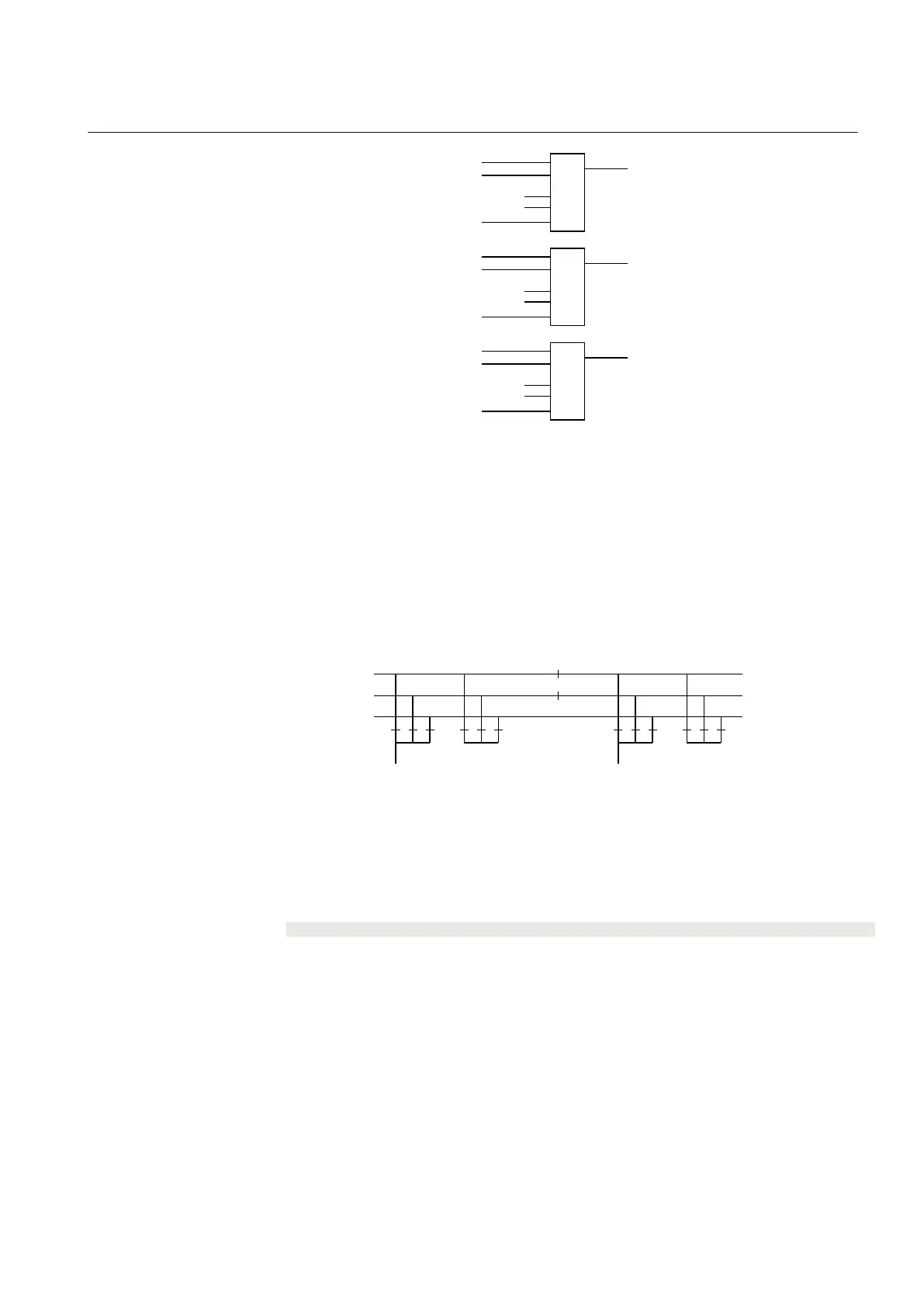
QB7OPTR (bay 1)
QB7OPTR (bay 2)
. . .
. . .
QB7OPTR (bay n-1)
&
BB7_D_OP
VPQB7TR (bay 1)
VPQB7TR (bay 2)
. . .
. . .
VPQB7TR (bay n-1)
&
VP_BB7_D
EXDU_BPB (bay 1)
EXDU_BPB (bay 2)
. . .
. . .
EXDU_BPB (bay n-1)
&
EXDU_BPB
en04000477.vsd
IEC04000477 V1 EN
Figure 243: Signals from bypass busbar in line bay n
15.3.2.3 Signals from bus-coupler
If the busbar is divided by bus-section disconnectors into bus sections, the busbar-
busbar connection could exist via the bus-section disconnector and bus-coupler within
the other bus section.
Section 1 Section 2
A1A2_DC(BS)
B1B2_DC(BS)
ABC_LINE ABC_BCABC_LINE ABC_BC
(WA1)A1
(WA2)B1
(WA7)C C
B2
A2
en04000479.vsd
IEC04000479 V1 EN
Figure 244: Busbars divided by bus-section disconnectors (circuit breakers)
To derive the signals:
Signal
BC_12_CL A bus-coupler connection exists between busbar WA1 and WA2.
BC_17_OP No bus-coupler connection between busbar WA1 and WA7.
BC_17_CL A bus-coupler connection exists between busbar WA1and WA7.
BC_27_OP No bus-coupler connection between busbar WA2 and WA7.
BC_27_CL A bus-coupler connection exists between busbar WA2 and WA7.
VP_BC_12 The switch status of BC_12 is valid.
VP_BC_17 The switch status of BC_17 is valid.
VP_BC_27 The switch status of BC_27 is valid.
EXDU_BC No transmission error from any bus-coupler bay (BC).
1MRK 502 071-UEN - Section 15
Control
Generator protection REG670 2.2 IEC and Injection equipment REX060, REX061, REX062 517
Application manual

 Loading...


