L
D
C
M
L
D
C
M
L
D
C
M
L
D
C
M
L
D
C
M
L
D
C
M
L
D
C
M
L
D
C
M
L
D
C
M
L
D
C
M
L
D
C
M
L
D
C
M
L
D
C
M
L
D
C
M
L
D
C
M
L
D
C
M
en06000519-2.vsd
IEC06000519 V2 EN
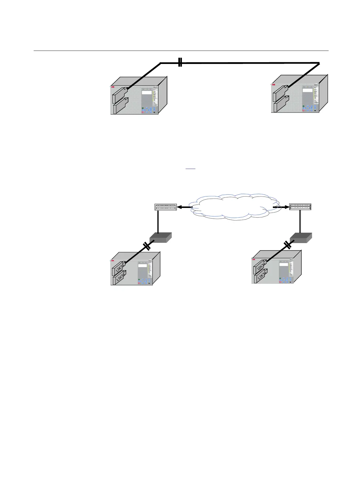
Figure 340: Direct fibre optical connection between two IEDs with LDCM
The LDCM can also be used together with an external optical to galvanic G.703
converter as shown in figure 341. These solutions are aimed for connections to a
multiplexer, which in turn is connected to a telecommunications transmission
network (for example PDH).
Telecom. Network
*) *)
Multiplexer Multiplexer
en05000527-2.vsd
*) Converting optical to galvanic G.703
IEC05000527 V2 EN
Figure 341: LDCM with an external optical to galvanic converter and a multiplexer
When an external modem G.703 is used, the connection between LDCM and the
modem is made with a multimode fibre of max. 3 km length. The IEEE/ANSI C37.94
protocol is always used between LDCM and the modem.
21.1.3 Setting guidelines
64 kbit and 2 Mbit mode common settings
ChannelMode defines how an IED discards the LDCM information when one of the
IEDs in the system is out of service: it can either be done on the IED out of service by
setting all local LDCMs to channel mode OutOfService or at the remote end by setting
1MRK 502 071-UEN - Section 21
Remote communication
Generator protection REG670 2.2 IEC and Injection equipment REX060, REX061, REX062 715
Application manual

 Loading...


