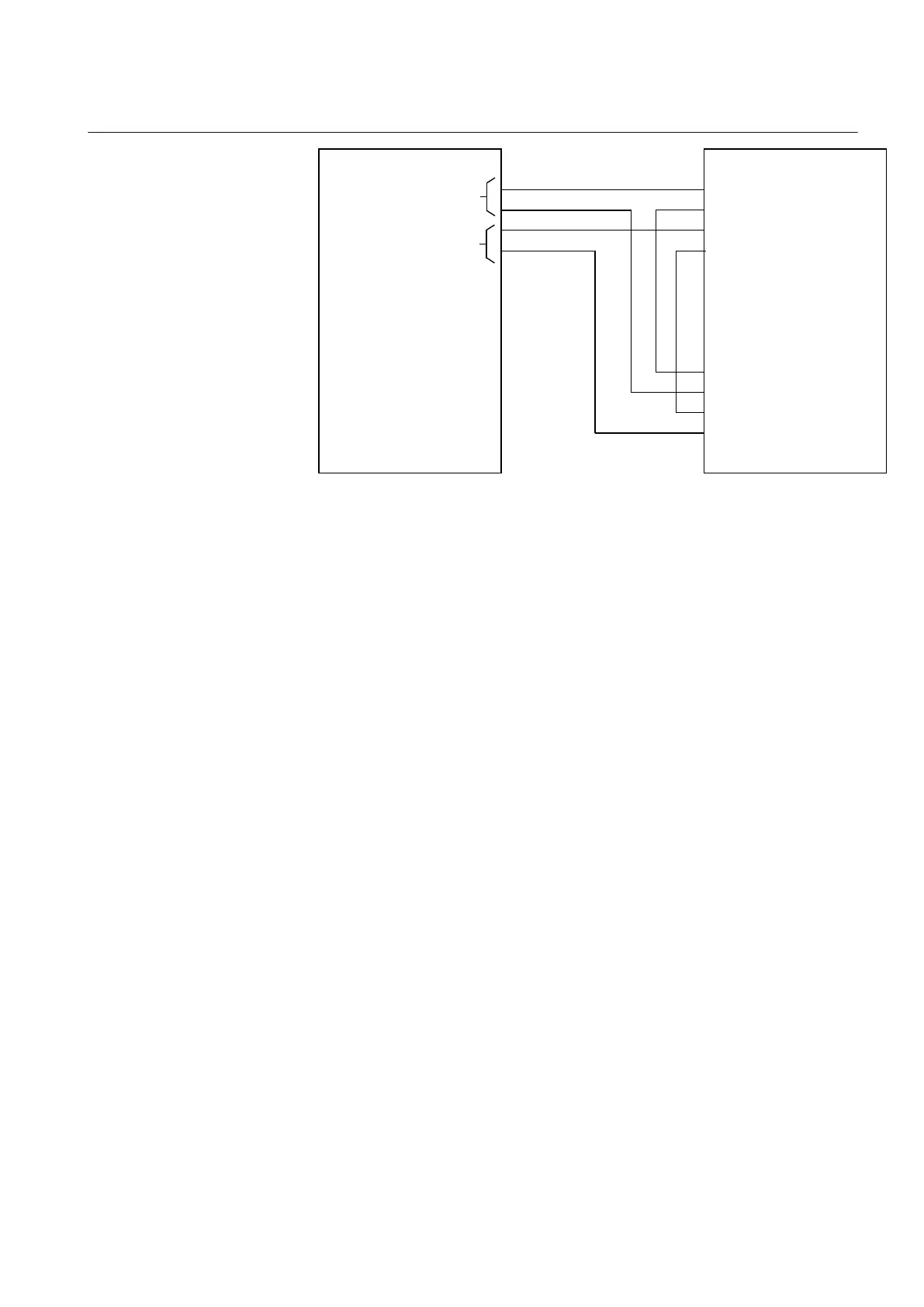
REX060
X61
9
8
8
9
11
10
11
10
X81
STATOR MODULE SIM
ROTOR MODULE RIM
IED
VOLTAGE MEASURE (U)
CURRENT MEASURE (U)
IEC11000210-1-en.vsd
IEC11000210 V1 EN
Figure 164: Connection to IED with two analogue voltage inputs
Some settings are required for the analog voltage inputs in the IED. The voltage ratio
for the inputs shall be set 1/1, for example, VTSecx = 100 V VTPrimx = 0.1 kV
The analogue inputs are linked to a pre-processor (SMAI) block in the Signal Matrix
Tool. This pre-processor block must have the same cycle time, 8 ms, as the function
block for STTIPHIZ.
The default parameter settings shall be used for the pre-processor block.
8.8.3.3 100% stator earth fault protection
Operation to be set On to activate the stator earth-fault protection
RTrip is the resistance level,set directly in primary Ohms, for activation of the trip-
function.
RAlarm is the resistance level, set directly in primary Ohms, for activation of the
alarm-function.
tAlarm is the time delay to activate the ALARM signal output when the measured fault
resistance is below the set RAlarm level
ULimRMS is a setting that controls the output URMSSTAT: if the total RMS voltage
measured by the function at the injection point is above the setting ULimRMS then the
output URMSSTAT is set to TRUE. The output URMSSTAT can be used in the logic
that selects the active reference impedance. The possibility to use this feature and the
1MRK 502 071-UEN - Section 8
Impedance protection
Generator protection REG670 2.2 IEC and Injection equipment REX060, REX061, REX062 307
Application manual

 Loading...


