The main CT ratios must also be set. This is done by setting the two parameters CTsec
and CTprim for each current channel. For a 1000/1 A CT, the following settings shall
be used:
• CTprim = 1000 (value in A)
• CTsec =1 (value in A).
4.2.2.4 Examples on how to connect, configure and set CT inputs for most
commonly used CT connections
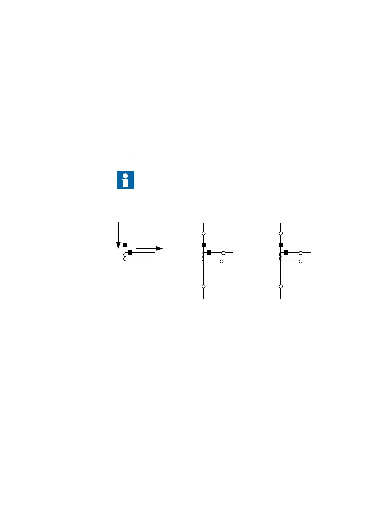
Figure 17 defines the marking of current transformer terminals commonly used
around the world:
In the SMAI function block, you have to set if the SMAI block is
measuring current or voltage. This is done with the parameter:
AnalogInputType: Current/Voltage. The ConnectionType: phase -
phase/phase-earth and GlobalBaseSel.
I
Sec
I
P
r
i
S1 (X1)
P1
(H1)
P2
(H2)
S2 (X2)
P2
(H2)
P1
(H1)
x x
a) b) c)
en06000641.vsd
S2 (X2)
S1 (X1)
IEC06000641 V1 EN
Figure 17: Commonly used markings of CT terminals
Where:
a) is symbol and terminal marking used in this document. Terminals marked with a square
indicates the primary and secondary winding terminals with the same (that is, positive) polarity
b) and c) are equivalent symbols and terminal marking used by IEC (ANSI) standard for CTs. Note that for
these two cases the CT polarity marking is correct!
It shall be noted that depending on national standard and utility practices, the rated
secondary current of a CT has typically one of the following values:
• 1A
• 5A
Section 4 1MRK 502 071-UEN -
Analog inputs
70 Generator protection REG670 2.2 IEC and Injection equipment REX060, REX061, REX062
Application manual

 Loading...


