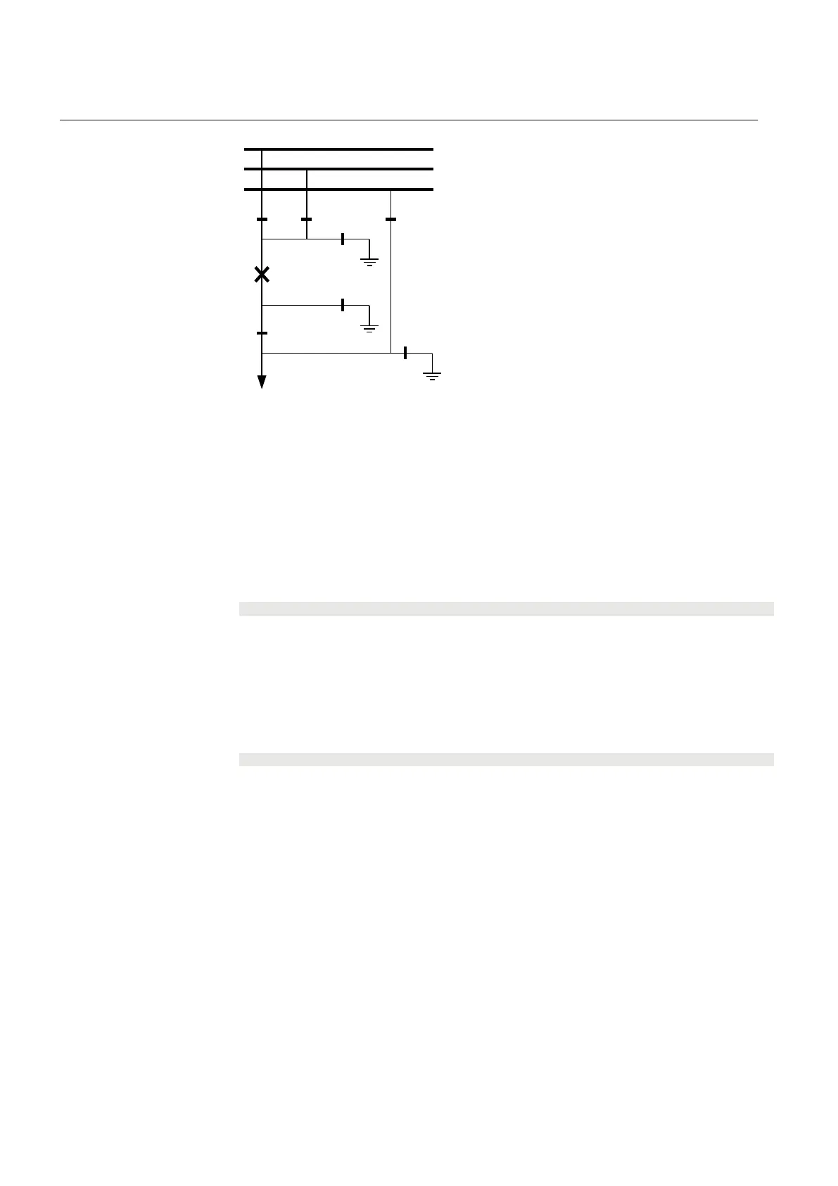
QB1 QB2
QC1
QA1
QC2
QB9
QC9
WA1 (A)
WA2 (B)
WA7 (C)
QB7
en04000478.vsd
IEC04000478 V1 EN
Figure 242: Switchyard layout ABC_LINE
The signals from other bays connected to the module ABC_LINE are described
below.
15.3.2.2 Signals from bypass busbar
To derive the signals:
Signal
BB7_D_OP All line disconnectors on bypass WA7 except in the own bay are open.
VP_BB7_D The switch status of disconnectors on bypass busbar WA7 are valid.
EXDU_BPB No transmission error from any bay containing disconnectors on bypass busbar WA7
These signals from each line bay (ABC_LINE) except that of the own bay are needed:
Signal
QB7OPTR Q7 is open
VPQB7TR The switch status for QB7 is valid.
EXDU_BPB No transmission error from the bay that contains the above information.
For bay n, these conditions are valid:
Section 15 1MRK 502 071-UEN -
Control
516 Generator protection REG670 2.2 IEC and Injection equipment REX060, REX061, REX062
Application manual

 Loading...


