WA1 (A)
WA2 (B)
QB1
QC1
QA1
QC2
QC9
QB61
QB9
QB2
QC4
QA2
QC5
QC3
QB62
DB_BUS_B
DB_LINE
DB_BUS_A
en04000518.vsd
IEC04000518 V1 EN
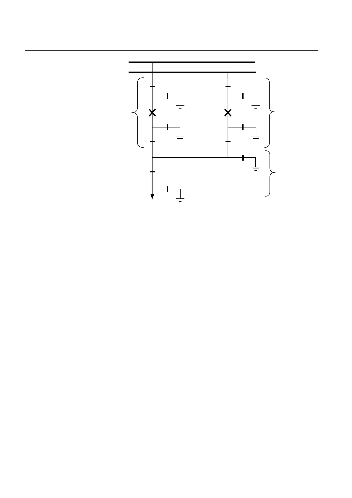
Figure 279: Switchyard layout double circuit breaker
For a double circuit-breaker bay, the modules DB_BUS_A, DB_LINE and
DB_BUS_B must be used.
15.3.8.2 Configuration setting
For application without QB9 and QC9, just set the appropriate inputs to open state and
disregard the outputs. In the functional block diagram, 0 and 1 are designated
0=FALSE and 1=TRUE:
• QB9_OP = 1
• QB9_CL = 0
• QC9_OP = 1
• QC9_CL = 0
If, in this case, line voltage supervision is added, then rather than setting QB9 to open
state, specify the state of the voltage supervision:
• QB9_OP = VOLT_OFF
• QB9_CL = VOLT_ON
If there is no voltage supervision, then set the corresponding inputs as follows:
• VOLT_OFF = 1
• VOLT_ON = 0
Section 15 1MRK 502 071-UEN -
Control
546 Generator protection REG670 2.2 IEC and Injection equipment REX060, REX061, REX062
Application manual

 Loading...


