At current transformer saturation a false residual current can be measured by the
protection. Here the 2
nd
harmonic restrain can prevent unwanted operation as well.
2ndHarmStab: The rate of 2nd harmonic current content for activation of the 2nd
harmonic restrain signal. The setting is given in % of the fundamental frequency
residual current.
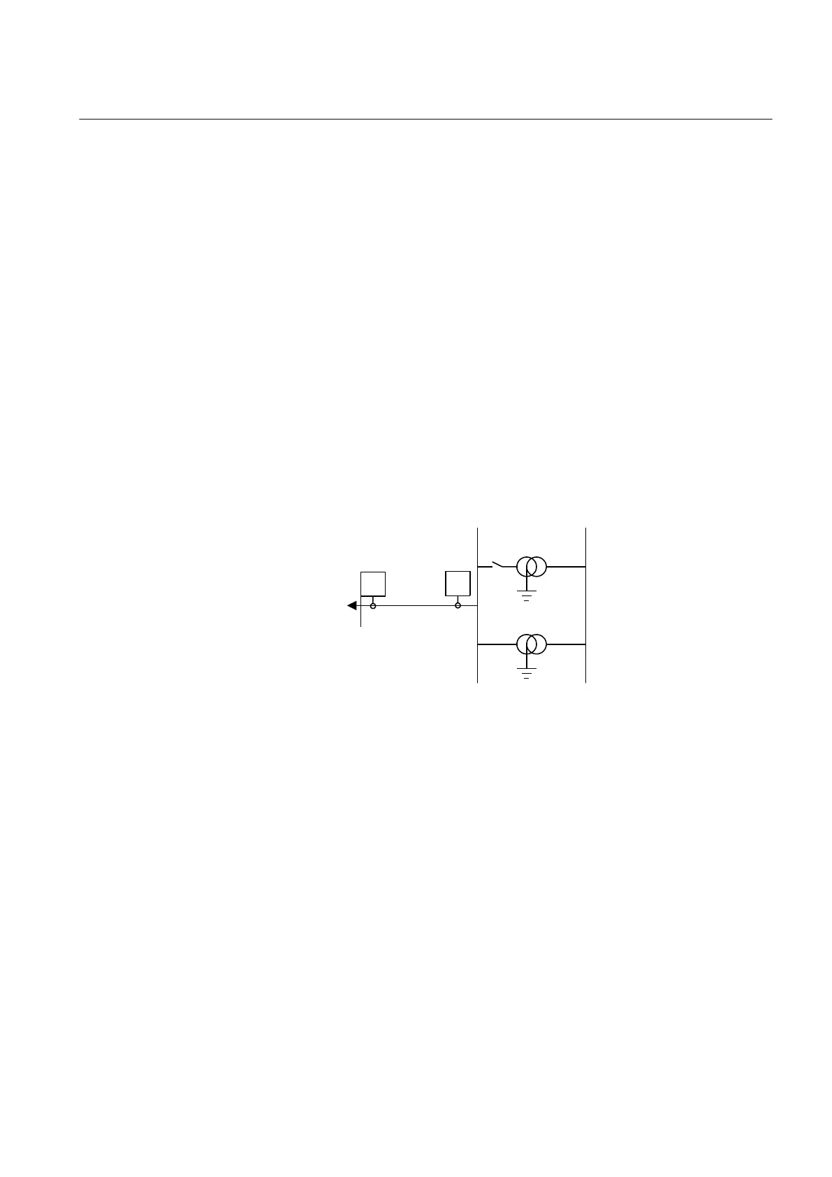
9.4.3.3 Parallel transformer inrush current logic
In case of parallel transformers there is a risk of sympathetic inrush current. If one of
the transformers is in operation, and the parallel transformer is switched in, the
asymmetric inrush current of the switched-in transformer will cause partial saturation
of the transformer already in service. This is called transferred saturation. The 2
nd
harmonic of the inrush currents of the two transformers will be in phase opposition.
The summation of the two currents will thus give a small 2
nd
harmonic current. The
residual fundamental current will however be significant. The inrush current of the
transformer in service before the parallel transformer energizing, will be a little
delayed compared to the first transformer. Therefore, we will have high 2
nd
harmonic
current initially. After a short period this current will however be small and the normal
2
nd
harmonic blocking will reset.
en05000136.vsd
Power System
IN>
IN>
IEC05000136 V1 EN
Figure 181: Application for parallel transformer inrush current logic
If the BlkParTransf function is activated, the 2
nd
harmonic restrain signal will latch as
long as the residual current measured by the relay is larger than a selected step current
level. Assume that step 4 is chosen to be the most sensitive step of the four step
residual overcurrent protection function EF4PTOC. The harmonic restrain blocking
is enabled for this step. Also the same current setting as this step is chosen for the
blocking at parallel transformer energizing.
The settings for the parallel transformer logic are described below.
BlkParTransf: This is used to On blocking at energising of parallel transformers.
UseStartValue: Gives which current level should be used for the activation of the
blocking signal. This is given as one of the settings of the steps: Step 1/2/3/4.
Normally, the step having the lowest operation current level should be set.
1MRK 502 071-UEN - Section 9
Current protection
Generator protection REG670 2.2 IEC and Injection equipment REX060, REX061, REX062 343
Application manual

 Loading...


