BC12CLTR (sect.1)
DCCLTR (A1A2)
DCCLTR (B1B2)
>1
&
BC12CLTR (sect.2)
&
VPBC12TR (sect.1)
VPDCTR (A1A2)
VPDCTR (B1B2)
VPBC12TR (sect.2)
>1
&
BC17OPTR (sect.1)
DCOPTR (A1A2)
BC17OPTR (sect.2)
>1
&
BC17CLTR (sect.1)
DCCLTR (A1A2)
BC17CLTR (sect.2)
&
VPBC17TR (sect.1)
VPDCTR (A1A2)
VPBC17TR (sect.2)
>1
&
>1
&
&
&
BC27OPTR (sect.1)
DCOPTR (B1B2)
BC27OPTR (sect.2)
BC27CLTR (sect.1)
DCCLTR (B1B2)
BC27CLTR (sect.2)
VPBC27TR (sect.1)
VPDCTR (B1B2)
VPBC27TR (sect.2)
EXDU_BC (sect.1)
EXDU_DC (A1A2)
EXDU_DC (B1B2)
EXDU_BC (sect.2)
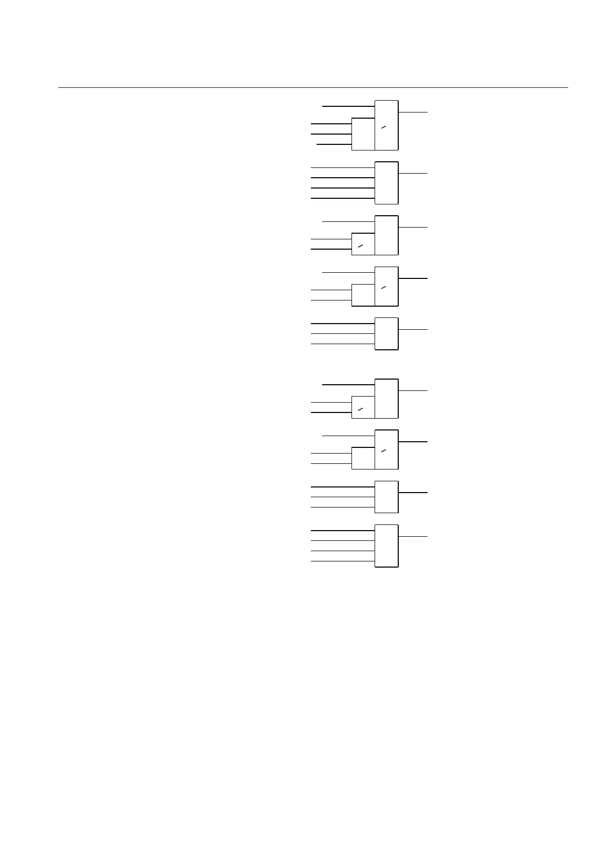
BC_12_CL
VP_BC_12
BC_17_OP
BC_17_CL
VP_BC_17
BC_27_OP
BC_27_CL
VP_BC_27
EXDU_BC
en04000480.vsd
IEC04000480 V1 EN
Figure 245: Signals to a line bay in section 1 from the bus-coupler bays in each
section
For a line bay in section 2, the same conditions as above are valid by changing section
1 to section 2 and vice versa.
15.3.2.4 Configuration setting
If there is no bypass busbar and therefore no QB7 disconnector, then the interlocking
for QB7 is not used. The states for QB7, QC71, BB7_D, BC_17, BC_27 are set to open
1MRK 502 071-UEN - Section 15
Control
Generator protection REG670 2.2 IEC and Injection equipment REX060, REX061, REX062 519
Application manual

 Loading...


