The settings of all the zones is provided in terms of percentage of impedance based on
current and voltage ratings of the generator.
8.9.2.2 Zone 1 operation
Zone 1 is used as fast selective tripping for phase-to-phase faults and three–phase
faults in the generator, on the terminal leads and LV side of generator transformer.
Since generator is high impedance earthed, the fault current for phase-to-earth faults
will be too low and impedance protection is not intended to operate for these faults.
The measuring loops used for zone1 are given below.
Zone 1 measuring loops for phase-to-phase faults and three–phase faults on the
primary side of the generator transformer are:
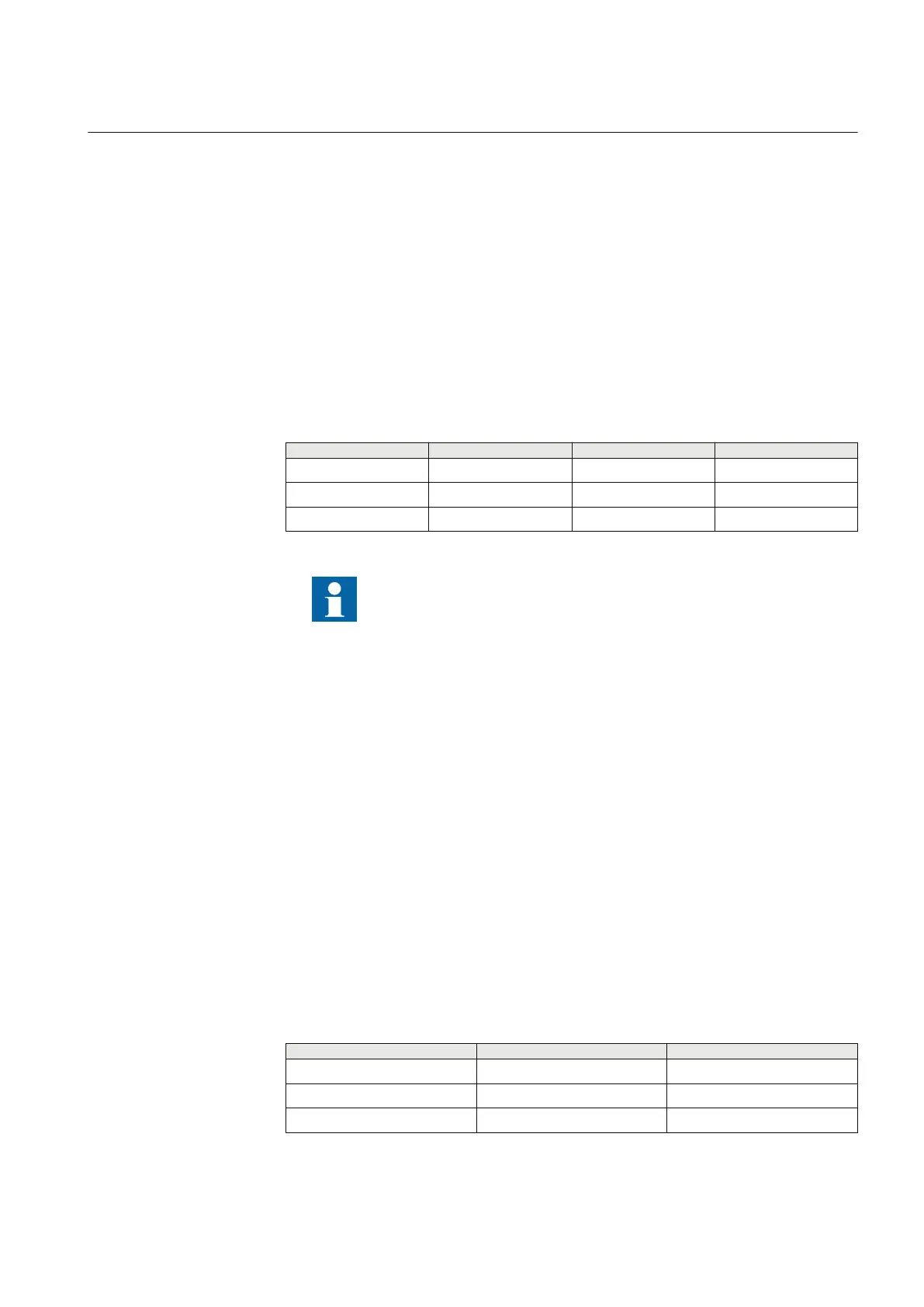
Sl.No Phase-to-phase loop Voltage phasor Current phasor
1 L1–L2 UL1L2 IL1L2
2 L2–L3 UL2L3 IL2L3
2 L3–L1 UL3L1 IL3L1
UL1L2, UL2L3, UL3L1 are three phase-to-phase voltages. IL1L2,
IL2L3, IL3L1 are the three phase-to-phase currents.
For this application the zone 1 element is typically set to see 75% of the transformer
impedance.
8.9.2.3 Zone 2 operation
Zone 2 can be used to cover up to the HV side of the transformer and the HV bus bar,
and is usually set to cover 125% of the generator transformer impedance. The time to
trip must be provided in order to coordinate with the zone 1 element on the shortest
outgoing line from the bus.
Zone2 will provide protection for phase-to-earth, phase-to-phase and three-phase
faults on the HV side of the system. All these faults can be detected using three phase-
to-phase loops or Enhanced reach loop (The phase-to-earth loop with maximum phase
current).
Two options are provided for measuring loops used for zone 2, which is set by the user.
The measuring loops used for zone 2 with different options are:
Phase-to-phase loops
Phase-to-phase loop
Voltage phasor Current phasor
L1–L2 UL1L2 IL1L2
L2–L3 UL2L3 IL2L3
L3–L1 UL3L1 IL3L1
1MRK 502 071-UEN - Section 8
Impedance protection
Generator protection REG670 2.2 IEC and Injection equipment REX060, REX061, REX062 311
Application manual

 Loading...


