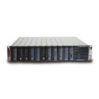
4-8 CHP Max™ Headend Optics Platform Chassis, Controllers and Power Supplies Rev D
Fan 1 current Displays fan 1 current in mA.
Configure Sets major low, minor low, minor high, and major high alarm limits of fan
1 and 2 currents.
Show info Lists the four alarm thresholds and graphical display configuration
information.
Show history Displays a graph of fan 1 current (mA) vs. time.
Save history Saves fan 1 current data points vs. time to an Excel file format.
Fan 2 current Displays fan 2 current in mA.
Configure Sets major low, minor low, minor high, and major high alarm limits of fan
1 and 2 currents.
Show info Lists the four alarm thresholds and graphical display configuration
information.
Show history Displays a graph of fan 2 current (mA) vs. time.
Save history Saves fan 2 current data points vs. time to an Excel file format.
Module Identity tab
This tab only provides status. Refer to Figure 4.5 on page 4-9 to see the various module parameters.
Alarms tab
This tab lists all major and minor alarms as shown in Figure 4.6 on page 4-9.
Table 4.3 Controls and Functions of the Craft Management Software (cont’d)
Control Function

 Loading...