Hardware Installation Manual 14 Document #: LTRT-94720
Mediant 3000
3.1.1 Front Panel Description
The main components of the device's front panel (without blade interfaces) are shown
below:
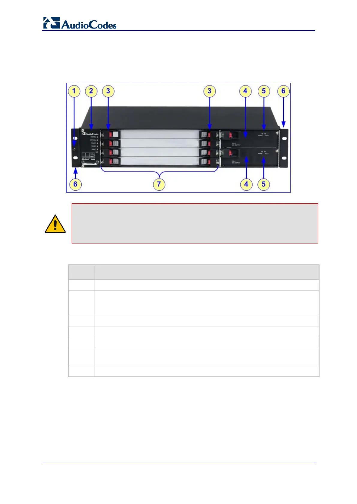
Figure 3-1: Chassis Front Panel
Notes:
• For clarity, the figure above displays the device without communication blades.
• Depending on the ordered configuration (e.g., AC or DC power system), your device
may differ from the figure above.
Table 3-1: Front-Panel Description
Item # Component Description
1
Electrostatic discharge (ESD) terminal.
2
Fan Tray module (housing the Air Filter), providing system alarm LEDs, ACO
button, and component location diagram indicating numbering of blade slots and
Power Supply units.
3
Latches and screws for securing blades to chassis.
4
Power Supply units.
5
Power Supply LEDs.
6
Integral mounting brackets for mounting the chassis in a standard 19-inch Telco
rack.
7
Blade slots (currently covered with blank panels) for housing the blades.
 Loading...