Version 7.0 59 Mediant 3000
Hardware Installation Manual 5. Cabling the Device
E1/T1 Number
(1 to 25)
RTM-8410 in Slot #2
E1/T1 Number
(43 to 67)
RTM-8410 in Slot #4
Tx Pins
(Tip / Ring)
Rx Pins
(Tip / Ring)
23 65 46 / 45 96 / 95
24 66 48 / 47 98 / 97
25 67 50 / 49 100 / 99
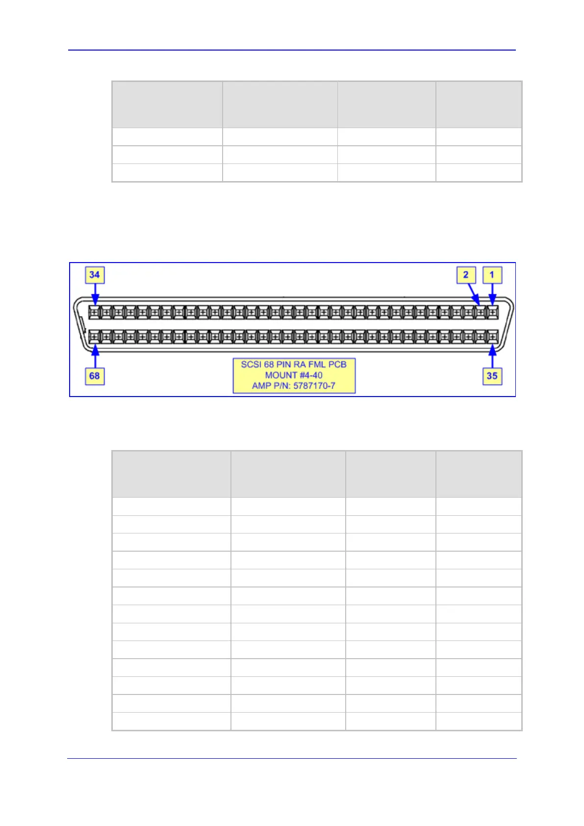
5.3.1.3 68-Pin SCSI Connector Specifications
The 68-pin female SCSI connector on the RTM-8410 is shown in the figure below.
Figure 5-9: 68-Pin SCSI Female Connector on RTM-8410 Blade
This connector must mate with a male connector that is wired according to the connector
pinouts in the subsequent table.
Table 5-6: E1/T1 Connections 26 to 42 on the 68-pin SCSI Connector Pinouts
E1/T1 Number
(26 to 42)
RTM-8410 in Slot #2
E1/T1 Number
(68 to 84)
RTM-8410 in Slot #4
Tx Pins
(Tip / Ring)
Rx Pins
(Tip / Ring)
26 68 2 / 1 36 / 35
27 69 4 / 3 38 / 37
28 70 6 / 5 40 / 39
29 71 8 / 7 42 / 41
30 72 10 / 9 44 / 43
31 73 12 / 11 46 / 45
32 74 14 / 13 48 / 47
33 75 16 / 15 50 / 49
34 76 18 / 17 52 / 51
35 77 20 / 19 54 / 53
36 78 22 / 21 56 / 55
37 79 24 / 23 58 / 57
38 80 26 / 25 60 / 59
 Loading...