Hardware Installation Manual 60 Document #: LTRT-94720
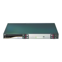
Mediant 3000
E1/T1 Number
(26 to 42)
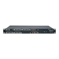
RTM-8410 in Slot #2
E1/T1 Number
(68 to 84)
RTM-8410 in Slot #4
Tx Pins
(Tip / Ring)
Rx Pins
(Tip / Ring)
39 81 28 / 27 62 / 61
40 82 30 / 29 64 / 63
41 83 32 / 31 66 / 65
42 84 34 / 33 68 / 67
5.3.1.4 Cabling Procedure
The procedure below describes how to cable the E1/T1 trunks
To connect the E1/T1 trunk interfaces:
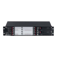
1. Prepare a SCSI cable of suitable length to connect between RTM-8410 housed in Slot
#2 and the PBX/PSTN switch. The connector at the RTM-8410 end of the cable should
be wired as shown in the tables below (one cable for the 100-pin connector and a
second cable for the 68-pin connector).
2. For 42- and 84-spans configurations:
a. Attach the trunk cable with a 100-pin male SCSI connector to the 100-pin female
SCSI connector labeled T1/E1 Trunks 1 to 25.
b. Attach the trunk cable with a 68-pin male SCSI connector to the 68-pin female
SCSI connector labeled T1/E1 Trunks 26 to 42.
c. For trunks 43 to 84, repeat steps 2.a and 2.b for the RTM-8410 housed in Slot #4.
3. For 16-spans configuration: attach the trunk cable with a 100-pin male SCSI
connector to the 100-pin female SCSI connector labeled T1/E1 Trunks 1 to 16.
4. Connect the other end of the trunk cables to the PBX/PSTN switch.
Note:
For RTM-8410 in Slot #4, ignore the trunk numbers printed on the two SCSI
connectors.
 Loading...