Hardware Installation Manual 32 Document #: LTRT-94720
Mediant 3000
3.4.2 RTM-8410 Rear Transition Module
The RTM-8410 (housed in the rear panel) operates with TP-8410 blade (housed in the front
panel). These two blades connect through the chassis midplane. RTM-8410 provides and
routes DS1 (E1/T1) PSTN interfaces to the TP-8410 blade. RTM-8410 also provides two
Gigabit Ethernet interfaces (RJ-45 ports or fiber optic SPF modules) for connection to the
LAN (IP network), using Cat 5 or fiber optic cables, respectively.
The type and quantity of RTM-8410 required depends on the number of supported E1/T1
interfaces, as listed in the table below:
Table 3-13: Type and Quantity of RTM-8410 per E1/T1 Span Configuration
E1/T1 Span Configuration RTM-8410 Type and Quantity
Fixed 16 E1 / 21 T1 One RTM-8410 providing a single SCSI connector (see
Section 3.4.2.1 on page 32).
Scalable from 16 E1 / T1 to
32 E1 / 42 T1
Two RTM-8410s, each providing two SCSI connectors,
but only one RTM is cabled (see Section 3.4.2.2 on page
32).
Scalable from 32 E1 / 42 T1
to 63 E1 / 84 T1
Two RTM-8410s, each providing two SCSI connectors for
42 E1 / T1 spans (see Section 3.4.2.2 on page 32).
Fixed 63 E1 / 84 T1 Two RTM-8410s, each providing two SCSI connectors for
42 E1 / T1 spans (see Section 3.4.2.2 on page 32).
Note: For blade slot assignment in the chassis, see Section 3.2.2 on page 16.
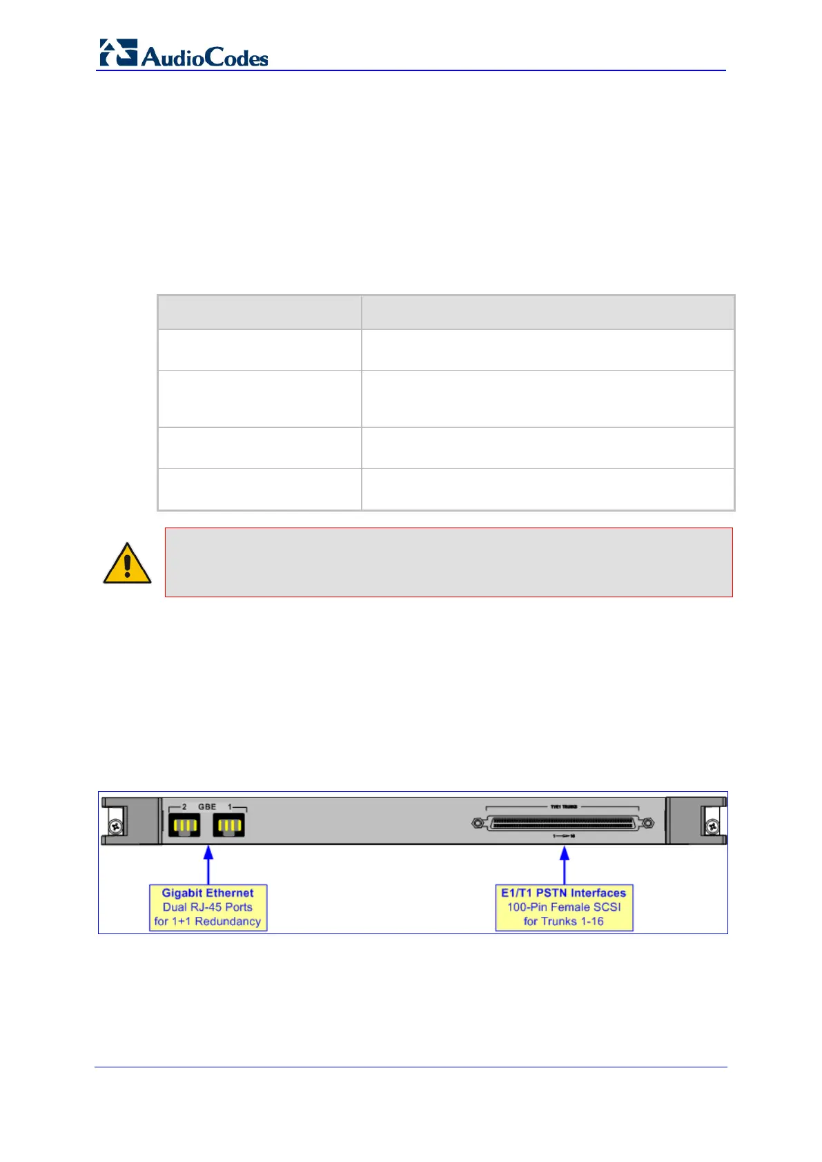
3.4.2.1 RTM-8410 for 16-Span Configuration
The RTM-8410 for fixed 16 E1 / 21 T1 span configuration includes the following port
interfaces:
A 100-pin female SCSI connector for E1/T1 trunks 1-16
Two RJ-45 GbE ports (for 1+1 Ethernet redundancy)
This RTM is housed in Slot #2 on the rear panel.
Figure 3-12: RTM-8410 for 16 Spans (Single SCSI Port)
 Loading...