Version 7.0 43 Mediant 3000
Hardware Installation Manual 3. Physical Description
3.8.2.1 DC Power Entry Module
The device's chassis is supplied with two PEM/DC/3K DC Power Entry Modules (PEM)
modules (housed in its rear panel), for connecting the device's chassis to the DC power
sources. The dual PEMs allow connection to two independent DC power sources, providing
electrical input (power) redundancy (High Availability) in the event of a failure in one of the
DC power sources. The device uses complete power entry separation between the two
existing DC power supplies in the system.
Each PEM is connected to its corresponding Power Supply module (see Section 3.8.2.2 on
page 44) located on the front panel. In other words, the upper PEM connects to the upper
Power Supply module; the lower PEM connects to the lower Power Supply module.
Therefore, when a fault is detected on a PEM module, its corresponding Power Supply
module becomes inactive. In normal operation, both PEMs should be cabled to a power
supply. When both PEMs are powered, both Power Supply modules provide power
simultaneously to the device.
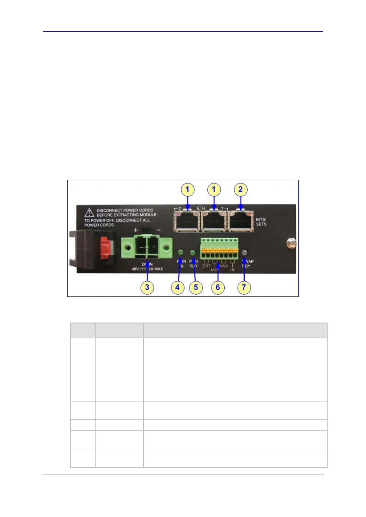
Figure 3-21: DC Power Entry (PEM/DC/3K) Module
The table below describes the PEM module's connectors and LEDs.
Table 3-21: DC Power Entry (PEM/DC/3K) Module Description
Item # Label Description
1
ETH
PEM with 6310 blades: N/A (GbE interface is provided by
the Ethernet ports on RTM-6310).
PEM with 8410 blades: Two 10/100BaseT Ethernet
interfaces (RJ-45 ports) for connection to OAMP and Control
(optional) networks for the Physical Network Separation
feature. For more information, see Section 5.3.2 on page 61.
Their operating status is provided by the ETH LEDs on the
8410 blade (see Section 3.4.1 on page 28).
2
BITS/SETS
Standard E1/T1 RJ-48 connector for synchronization and timing
source.
3
DC IN
-48 VDC power inlet.
4
PWR IN
Power LED (green color) - incoming primary voltage (-48 VDC)
detected.
5
PEM RDY
Backplane power is alive (secondary PEM power is normal and
active). The LED lights up green.
 Loading...