Hardware Installation Manual 30 Document #: LTRT-94720
Mediant 3000
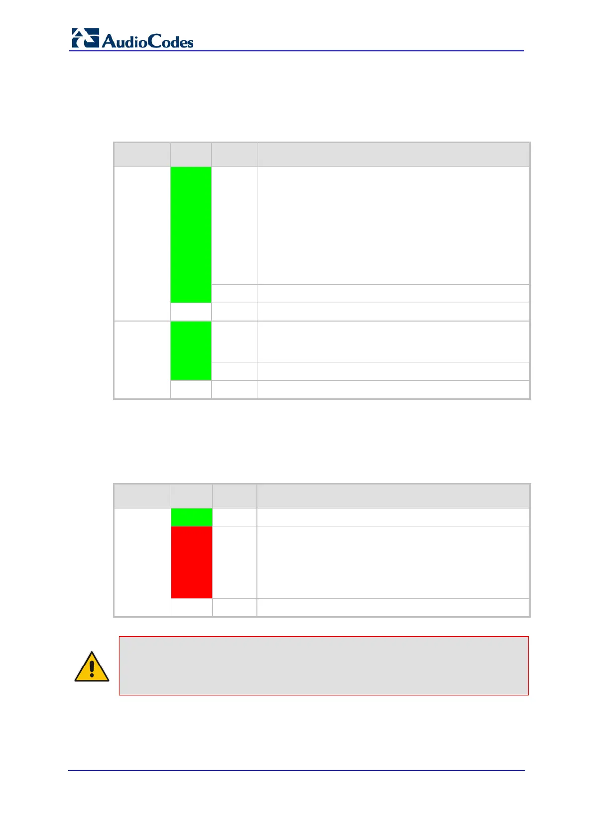
3.4.1.2 Ethernet LEDs
The Ethernet LEDs are described in the table below.
Table 3-11: Ethernet LEDs Description
Label Color Status Description
ETH
(1A, 1B,
2A, 2B)
Green
On 10/100BaseT Ethernet link is established. For the status of
the Ethernet ports on the PEM module, see Section 3.8 on
page 37.
A LEDs: status of the Ethernet ports located on the
lower PEM module.
B LEDs: status of the Ethernet ports located on the
upper PEM module.
1A and 1B: status of the Control network interface.
2A and 2B: status of the OAMP network interface.
Blinking Data is being transmitted or received.
-
Off No Ethernet link.
GBE
(1, 2)
Green
On Gigabit Ethernet link is established. This LED indicates
Media network traffic. For the status of the Ethernet ports
on RTM-8410, see Section 3.4.2 on page 32.
Blinking Data is being transmitted or received.
-
Off No Gigabit Ethernet link.
3.4.1.3 PSTN (E1/T1) LEDs
The PSTN LEDs are described in the table below.
Table 3-12: PSTN E1/T1/J1 LEDs Description
Label Color Status Description
E1 / T1
(1 - 8)
Green
On E1/T1 is synchronized.
Red
On Traffic loss due to one of the following signals:
LOS (Loss of Signal)
LFA (Loss of Frame Alignment)
AIS (Alarm Indication Signal) - 'Blue Alarm'
RAI (Remote Alarm Indication) - 'Yellow Alarm'
-
Off No link.
Note: The E1/T1 LEDs display only eight E1/T1 trunks at a time. The trunk numbers for
which the LEDs are currently relevant are displayed in the LED Array Display. To view
the next consecutive group of eight trunks and for a description of the LED Array Display,
see Section 3.4.1.4 on page 31.
 Loading...