Version 7.0 37 Mediant 3000
Hardware Installation Manual 3. Physical Description
3.7 Alarm LEDs and ACO Button
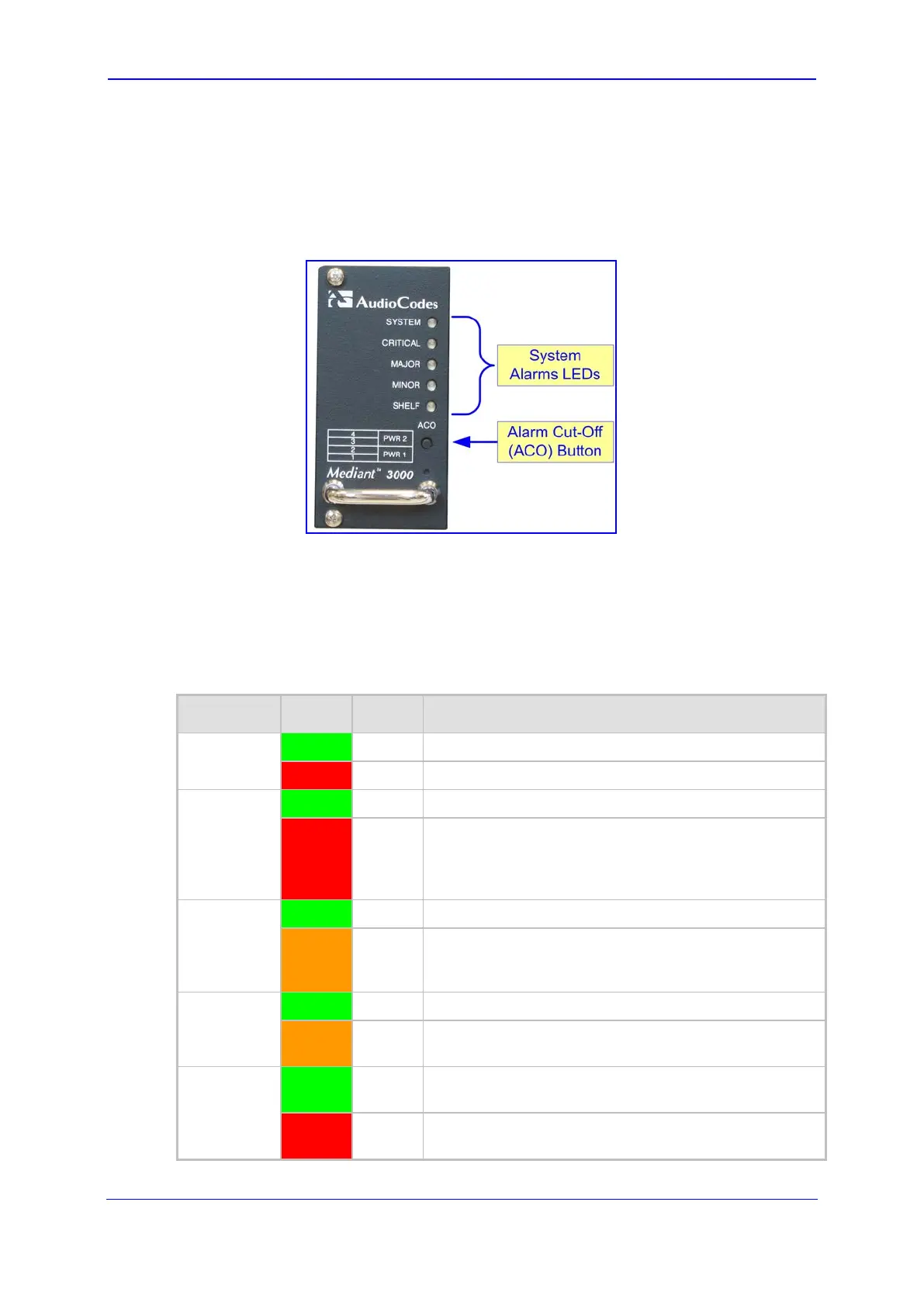
The front panel of the Fan Tray module provides fault detection severity alarm LEDs and an
Alarm Cut-Off (ACO) button, as shown in the figure below:
Figure 3-18: Fan Tray Module with Alarm LEDs and ACO Button
The ACO button is used to mute the external Telco alarm relay devices attached to the
Power Entry Module (see Section 3.7 on page 37). When the ACO button is pressed, all
alarm relays are returned to normal position, de-activating the alarm relay devices. The
chassis LEDs and other device alarm signals are not affected.
The fault detection alarm LEDs (described in the table below) are connected to the Alarm,
Status and Synchronization blade.
Table 3-15: Fan Tray Module Alarm LEDs Description
LED Color Status Description
SYSTEM Green
On Normal operation.
Red
On System failure.
CRITICAL Green
On No Critical alarms.
Red
On (Default when the device is powered on.) Detection of a
fault(s) categorized as “Critical” (i.e., Critical alarm).
When this LED is on, the MAJOR and MINOR LEDs
are also lit.
MAJOR Green
On No Major alarms.
Orange
On (Default when the device is powered on.) Detection of a
fault(s) categorized as “Major” (i.e., Major alarm). When
this LED is on, the MINOR LED is also lit.
MINOR
Green
On No Minor alarms.
Orange
On (Default when the device is powered on.) Detection of a
fault(s) categorized as "Minor" (i.e., Minor alarm).
SHELF
Green
On Initialization completed successfully (i.e., normal
functioning of the chassis hardware).
Red
On (Default when the device is powered on.) Undergoing
initialization (or failure of the chassis hardware).
 Loading...