18. Lamp power supply (single module)
Image 18-7
Fixation fram e
4. Secure the 4 spring screws ( 1).
2
3
1
1
Image 18-8
Fixation screws and power connection
5. Connect the grounding wire (PE wire) mounted on the LPS fix ation into the socket of the LPS unit (2, image 18-8.
6. Connect the mains input cables with the MAINS INPUT sockets of each LP S m odule as illustrated (3, image 18-8).
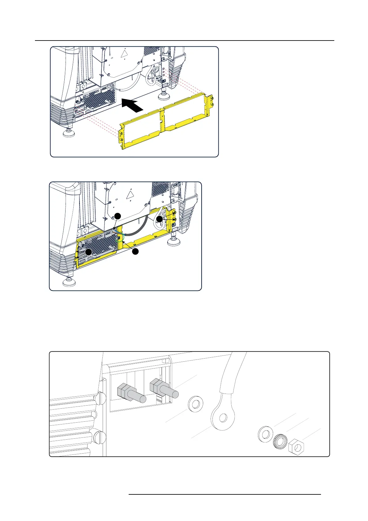
7. Connect the power cables coming from the S PG module w ith t he LAMP OUT sockets of the LP S module as illustrated. Fasten
the nuts with a torque of 4Nm (2.95 lbf*ft).
Warning: Make su re to p lace the w ashers and cable eyes in correct order upon the pin as illustrated. Alw ays u se a plain
washer between the output pin and the cable eyes.
L
N
P
W
E1
W
Image 18-9
Lamp out connection
P LPS output pin.
W Plain w asher.
L Lock washer.
R5905043 DP2K-12C/11CX 19/02/2018 297
 Loading...


