32.12
•
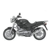
Remove connection cable, brake lines and Bow-
den cable from brackets (arrows)
•
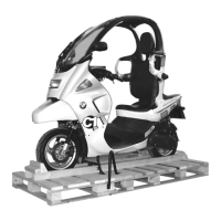
Remove the fasteners (arrows) securing the han-
dlebar
When installing:
•
While installation is basically a reversal of the re-
moval process, careful attention should be di-
rected toward the following:
d
Warning:
Make sure that the gaps at the clamps for the brake-
control assemblys are of uniform width!
e
Attention:
Ensure that lines and Bowden cables are routed
correctly!
Ensure that brake switch and combination switch
are positioned correctly!
Ensure adequate clearance between combination
switch and brake-control assembly!
•
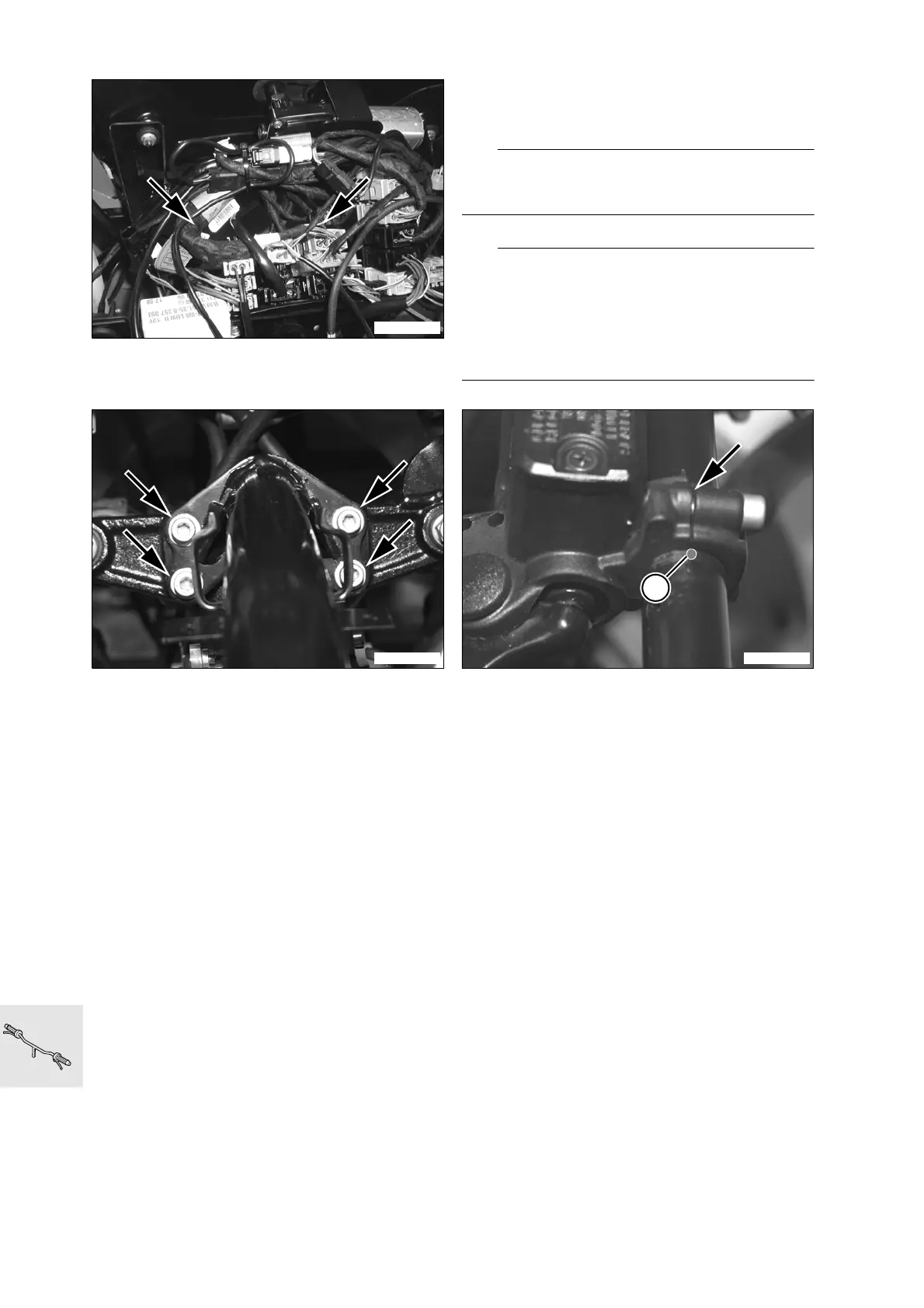
Align the hand fittings with the punch marks (1)
•
Uniformly tighten clamping screws
•
Make sure that the gap (arrow) at the clamp is of
uniform width
•
Check throttle cable play, adjusting if necessary
Adjustment data:
Move the handlebars all the way from left to right
and ensure that throttle valve does not move
X
Torque specification:
Handlebar mount ......................................... 21 Nm
Brake-control assembly pinch bolts ............... 9 Nm
Combination switch mount............................. 4 Nm
C1320100
C1320110 C1320090
1
 Loading...