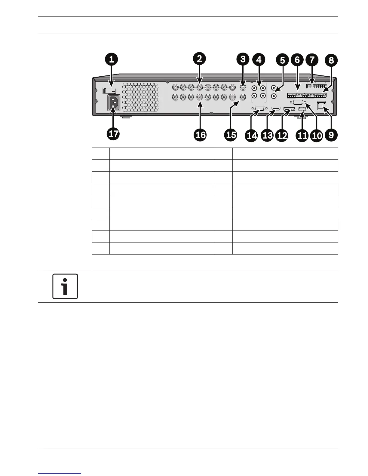
1 Power ON/OFF switch 10 RS232 connector for Dome control
2 Camera VIDEO IN BNC connectors 11 USB connector
3 CVBS output - Monitor A 12 e-SATA connector
4 Audio inputs 13 HDMI output - Monitor A
5 Audio output and MIC IN connector 14 VGA output - Monitor A
6 Alarm outputs 15 CVBS output - Monitor B
7 Alarm inputs 16 VIDEO OUT (loop through)
8 RS485 and keyboard connectors 17 Power connector
9 RJ45 ethernet connector
Notice!
The 4-channel DIVAR AN 5000 models have a slightly different back panel (VIDEO IN/OUT
connectors 5 to 8 are disabled).
Primary connections
1. Connect the cameras to the VIDEO IN BNC connectors.
2. Connect monitor A to the VGA MON A output, or the HDMI MON A output, or the CVBS
MON A output.
3. Connect the USB mouse to a USB port (front or back panel).
For first time use, the NTSC or PAL selection is determined by the camera type connected to
VIDEO IN 1 in step 1. If no camera is connected to VIDEO IN 1 during first time use, the video
standard is default and can be set in the Startup Wizard.
Optional connections
1. Connect monitor B to the CVBS MON B connector.
2. Connect up to 4 audio signals to the AUDIO IN RCA (CINCH) inputs.
3. Connect 1 microphone to the MIC IN RCA (CINCH) output.
4. Connect 1 AUDIO OUT RCA (CINCH) output to the monitor or an audio amplifier.
5. Connect up to 16 ALARM IN inputs (via the supplied terminal blocks).
4.1.1
4.1.2
DIVAR AN 3000 / DIVAR AN 5000 Quick install | en 19
Bosch Security Systems Operations Manual 2014.10 | 2.0 | AM18-Q0669
 Loading...