Trouble Shooting Information for C7000VP series
8.4 Points to note when collecting Sublog
Very detailed logs are collected as Sublog, so if the time passes after the failure occurrence,
you lose track of the failure log. Regardless of the RB-SRAM UNIT equipment, the log needs to
be collected right after the failure occurrence.
8.5 When RB- SRAM UNIT Is Not Equipped
Even when RB-SRAM UNIT is not equipped, BW3/CL2 controller-equipped models can secure
the 2MB memory capacity in DRAM and collect the Sublog of approx. 30,000 lines (in text). If
the Sublog is collected right after the failure occurrence with the good timing, very useful
Sublog can be collected.
8.6 How to Collect Sublog
8.6.1 Overview of Sublog collection procedures
Collect the Sublog with the following procedures. The details are described later.
As for iPRC7000VP and following products, multiple Sublog files can be collected by the
auto-collection.
1. Equip the RB-SRAM UNIT on the controller PCB of iPRC7000VP.
(Even this unit is not equipped, 2MB logs can be collected using DRAM.)
2. Make a failure.
3. Write the Sublog data stored on SRAM or DRAM to the device’s HDD as a file.
4. Collect the Sublog file in the HDD. (Collection method is either one of the following.)
4-1. SST is used.
4-2. USB memory is used.
5. Report the collected Sublog to CINC when reporting the failure.
8.6.2 Details of Sublog collection procedures
1. Equipping RB-SRAM UNIT
Turn off the main power and implement anti-static measures.
1. Remove 8 screws to remove the rear cover of Power Unit Station (which the controller PCB
is equipped).
2. Remove 10 screws to remove the controller cover, so that HDD unit and main controller can
be accessed.
3. Remove 2 power cables for HDD and 2 IDE cables from the plug. Remove 4 screws to
remove the HDD unit.
4. Remove the RB-A PCB equipped on the left side of controller PCB. Store the removed
RB-A PCB.
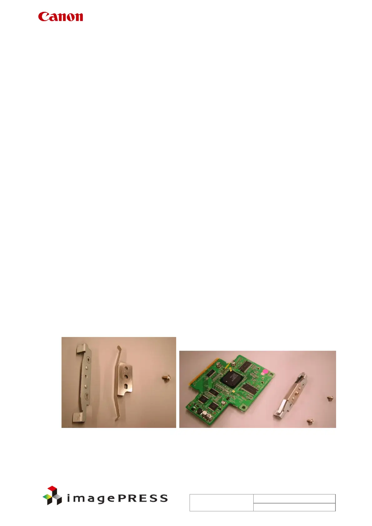
5. Assemble 2 metal plates using 1 screw. (Figure 1)
Figure 1 Assembling metal plates
 Loading...