ANTILOCK BRAKE SYSTEM 4F–7
DAEWOO M-150 BL2
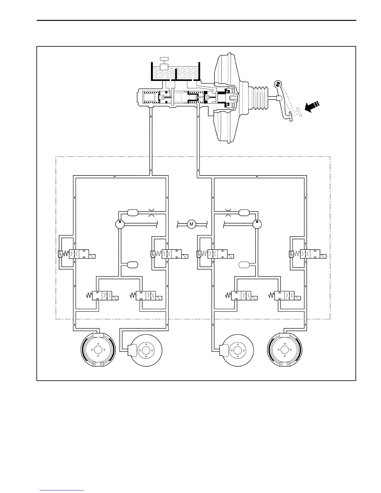
HYDRAULIC FLUID FLOW DIAGRAMS
Master Cylinder
High Pressure Attenuator
High Pressure Attenuator
Return Pump Motor
Return Pump
Return Pump
RR
Isolation Valve
Low
Pressure
Accumulator
FL
Isolation Valve
RR Dump Valve
FL
Dump
Valve
FR
Isolation Valve
Low Pressure
Accumulator
FR Dump Valve
RL
Dump
Valve
RL
Isolation
Valve
RR FL FR RL
D17E205A
NORMAL BRAKE MODE
During non-antilock braking, pressure is applied through the brake pedal and fluid comes from the master cylinder into
the hydraulic unit. The normally open isolation cartridge and normally closed dump cartridge would remain in these
positions to allow fluid pressure to the calipers and the wheel cylinders. And each wheel begins locking.
 Loading...