7B -- 30 MANUAL CONTROL HEATING, VENTILATION, AND AIR CONDITIONING SYSTEM
DAEWOO M-150 BL2
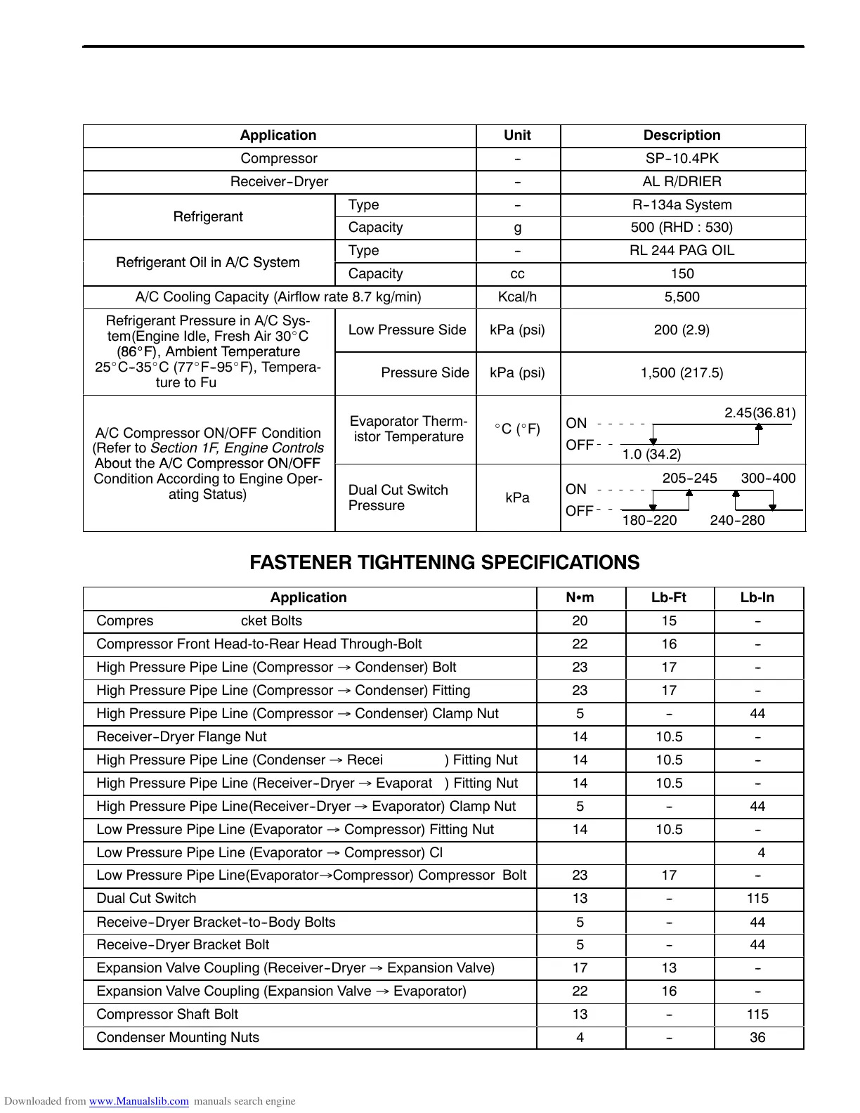
SPECIFICATIONS
GENERAL SPECIFICATIONS
Application
Unit
Description
Compressor
--
SP--10.4PK
Receiver--Dryer
--
AL R/DRIER
Type
--
R--134a System
e
r
gerant
Capacity
g
500 (RHD : 530)
Type
--
RL 244 PAG OIL
e
r
gerant
n
ystem
Capacity
cc
150
A/C Cooling Capacity (Airflow rate 8.7 kg/min)
Kcal/h
5,500
Refrigerant Pressure in A/C Sys-
tem(Engine Idle, Fresh Air 30_C
_
Low Pressure Side
kPa (psi)
200 (2.9)
_
,
m
ent
emperature
25_C--35_C(77_F--95_F), Tempera-
ture to Full Cold)
High Pressure Side
kPa (psi)
1,500 (217.5)
A/C Compressor ON/OFF Condition
(Refer to Section 1F, Engine Controls
Evaporator Therm-
istor Temperature
_C(_F)
2.45(36.81)
1.0 (34.2)
ON
OFF
out t
e
ompressor
Condition According to Engine Oper-
ating Status)
Dual Cut Switch
Pressure
kPa
205-- 245
180-- 220
ON
OFF
300-- 400
240-- 280
FASTENER TIGHTENING SPECIFICATIONS
Application
NSm
Lb-Ft
Lb-In
Compressor Upper Bracket Bolts
20
15
--
Compressor Front Head-to-Rear Head Through-Bolt
22
16
--
High Pressure Pipe Line (Compressor → Condenser) Bolt
23
17
--
High Pressure Pipe Line (Compressor → Condenser) Fitting
23
17
--
High Pressure Pipe Line (Compressor → Condenser) Clamp Nut
5
--
44
Receiver--Dryer Flange Nut
14
10.5
--
High Pressure Pipe Line (Condenser → Receiver--Dryer) Fitting Nut
14
10.5
--
High Pressure Pipe Line (Receiver--Dryer → Evaporator) Fitting Nut
14
10.5
--
High Pressure Pipe Line(Receiver--Dryer → Evaporator) Clamp Nut
5
--
44
Low Pressure Pipe Line (Evaporator → Compressor) Fitting Nut
14
10.5
--
Low Pressure Pipe Line (Evaporator → Compressor) Clamp Nut
5
--
44
Low Pressure Pipe Line(Evaporator→Compressor) Compressor Bolt
23
17
--
Dual Cut Switch
13
--
115
Receive--Dryer Bracket--to--Body Bolts
5
--
44
Receive--Dryer Bracket Bolt
5
--
44
Expansion Valve Coupling (Receiver--Dryer → Expansion Valve)
17
13
--
Expansion Valve Coupling (Expansion Valve → Evaporator)
22
16
--
Compressor Shaft Bolt
13
--
115
Condenser Mounting Nuts
4
--
36
 Loading...