ESIE11-02 Checking the Inputs and Outputs
Part 3 – Troubleshooting 3–17
33
4
5
1
3.5 Checking the Digital Inputs and Outputs
Troubleshooting In most cases a malfunction occurs in the unit itself and not in the control circuit of the unit. However,
if a malfunction does occur in the control circuit, measure the relevant signals using the schematic
input route shown below.
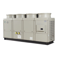
Input route to PCB The block diagram below shows the digital input route from the transducer (e.g. thermostat,
pressostat, reverse phase, etc.) to the PCB input.
Output route from
PCB
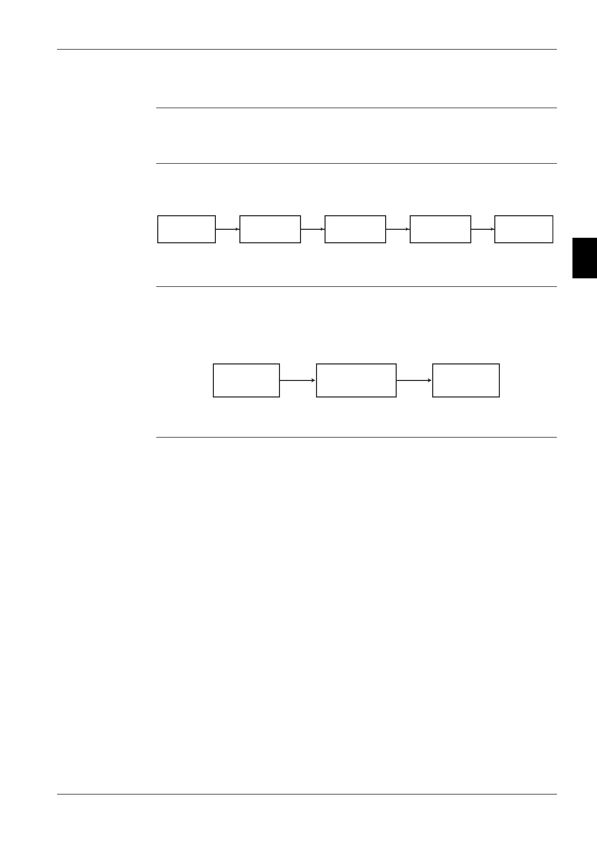
The output is generated by the PCB. If a device does not operate, you should find the relevant output
signal from the PCB in order to decide whether the PCB or the device needs replacement.
The block diagram below shows the output route.
Unit Transducer Relay
Relay contact
PCB input
Voltage free
contact
230 V (coil) Voltage free
contact
24 V AC
PCB output Control relay
Voltage free
contact
230 V (supply) E.g. fan, valve...
Device
 Loading...