Piping Layout ESIE11-02
1–60 Part 1 – System Outline
3
11
4
5
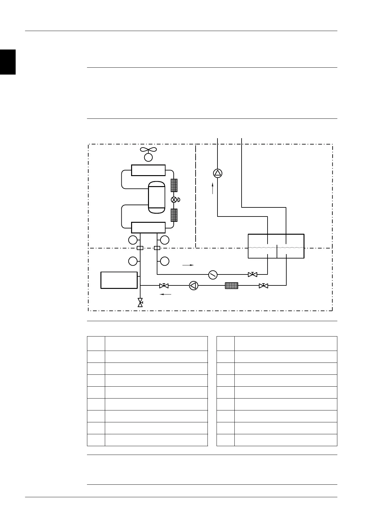
2.2 Installation outline
Introduction The installation outline contains the main parts of a typical installation:
■ Chiller
■ Primary water circuit
■ Secondary water circuit.
Typical installation The illustration below shows a typical installation. Some of these components may not be present in
all the chillers described in this manual.
Components The table below lists the components.
Water filter Make sure a filter is installed in front of the water inlet of the plate-heat exchanger. The plate-heat
exchangers are sensitive to dirt and small particles.
The mesh opening of the filter is max. 0.5 mm.
T1
P1
T2
P2
3
2
6
6
4
5
1
15
10
13
14
12
88
7
11
9
9
11
16
Chiller Secondary water circuit
Primary water circuit
No. Chiller No. Primary water circuit
1 Compressor 9 Pressure measuring points
2 Air-heat exchanger 10 Flow switch
3 Expansion valve 11 Shut-off valves
4 Water-heat exchanger 12 Buffer tank
5 Fan motor 13 Water filter
6 Refrigerant filter strainer 14 Water pump
7 Water connections 15 Drain valve
8 Temperature measuring points 16 Expansion tank
 Loading...