ESIE11-02 General Outline
Part 1 – System Outline 1–49
3
1
4
5
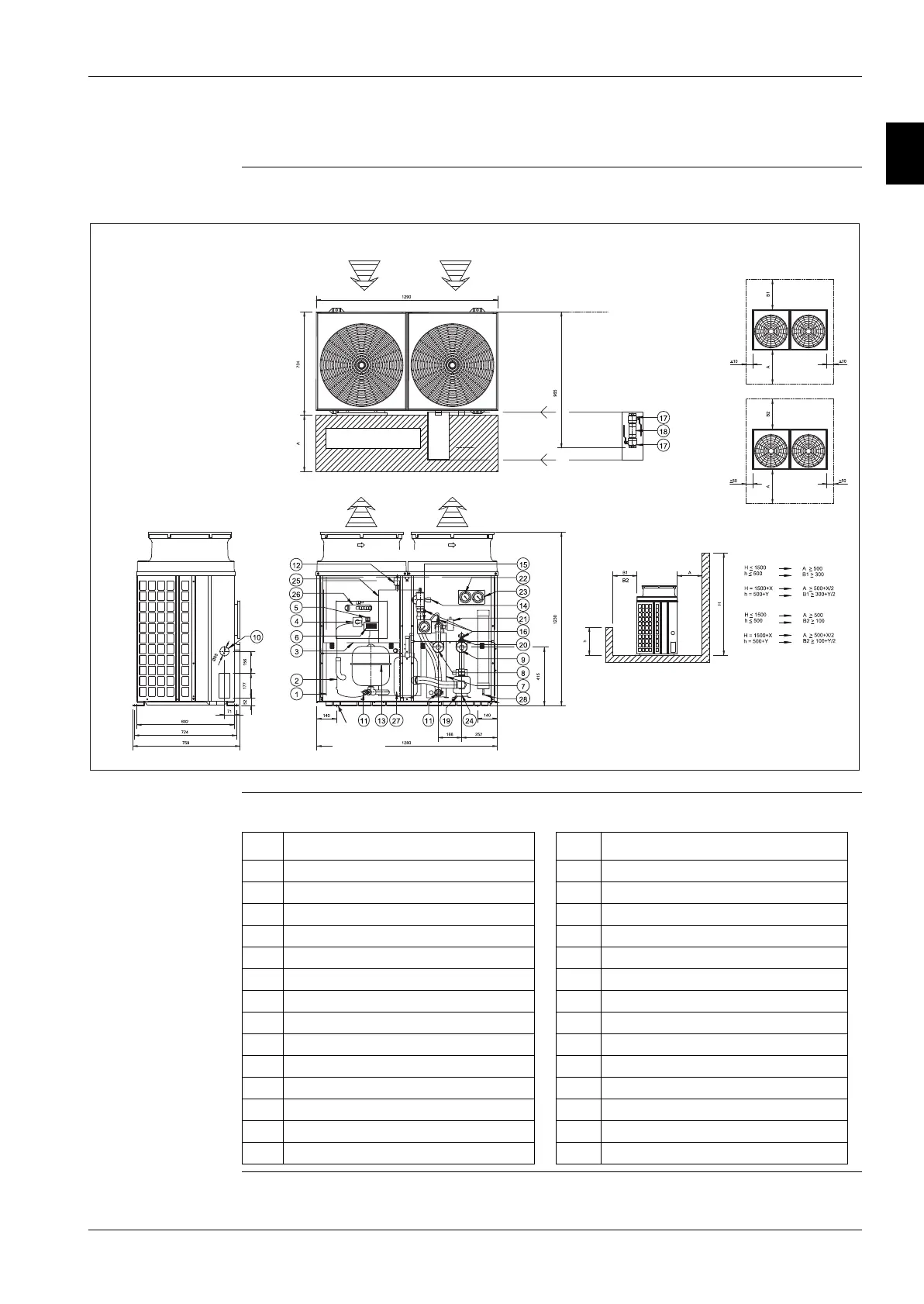
1.21 Outlook Drawing: EUWAB5-8KBZW1/EUWYB5-8KBZW1
EUWAB5-8KBZW1/
EUWYB5-8KBZW1
The illustration below shows the outlook, the dimensions and the installation and service space of the
unit (mm).
Components The table below lists the components.
FREE SPACE B1/B2
FREE SPACE MIN 3m
CAUTION FOR FAN
FIXATION
4XØ15
SERVICE SPACE
FILTERKIT
(delivered with the unit)
No. Component No. Component
1 Air heat exchanger 15 Manometer (water)
2 Compressor 16 Pressure port
3 Switch box 17 Ball valve: 1 1/4” BSP
4 Main switch 18 Water filter: 1 1/4” BSP
5 Pump switch 19 Pump
6 Digital display controller 20 Regulation valve
7 Water heat exchanger 21 Flow switch
8 Water IN connection: 1 1/4” M BSP 22 High pressure gauge (optional)
9 Water OUT connection: 1 1/4” M BSP 23 Low pressure gauge (optional)
10 Power supply intake 24 Pump drain
11 Drain 25 Buffertank
12 Air purge 26 4-way valve (only on H/P models)
13 Expansion vessel 27 Accumulator (only on H/P models)
14 Safety valve 28 Liquid receiver (only on H/P models)
 Loading...