ESIE11-02 Functional Description
Part 2 – Functional Description 2–11
3
2
4
5
1
1.8 Head Pressure Control: EUWA*5-24KBZW1 and EUWY*5-24KBZW1
Functional
description
■ The chillers are equipped with a fan control to limit the high pressure based on ambient
temperature.
■ Each circuit (K4A, K5A and K12A) has the same functionality.
Fan management in
cooling mode
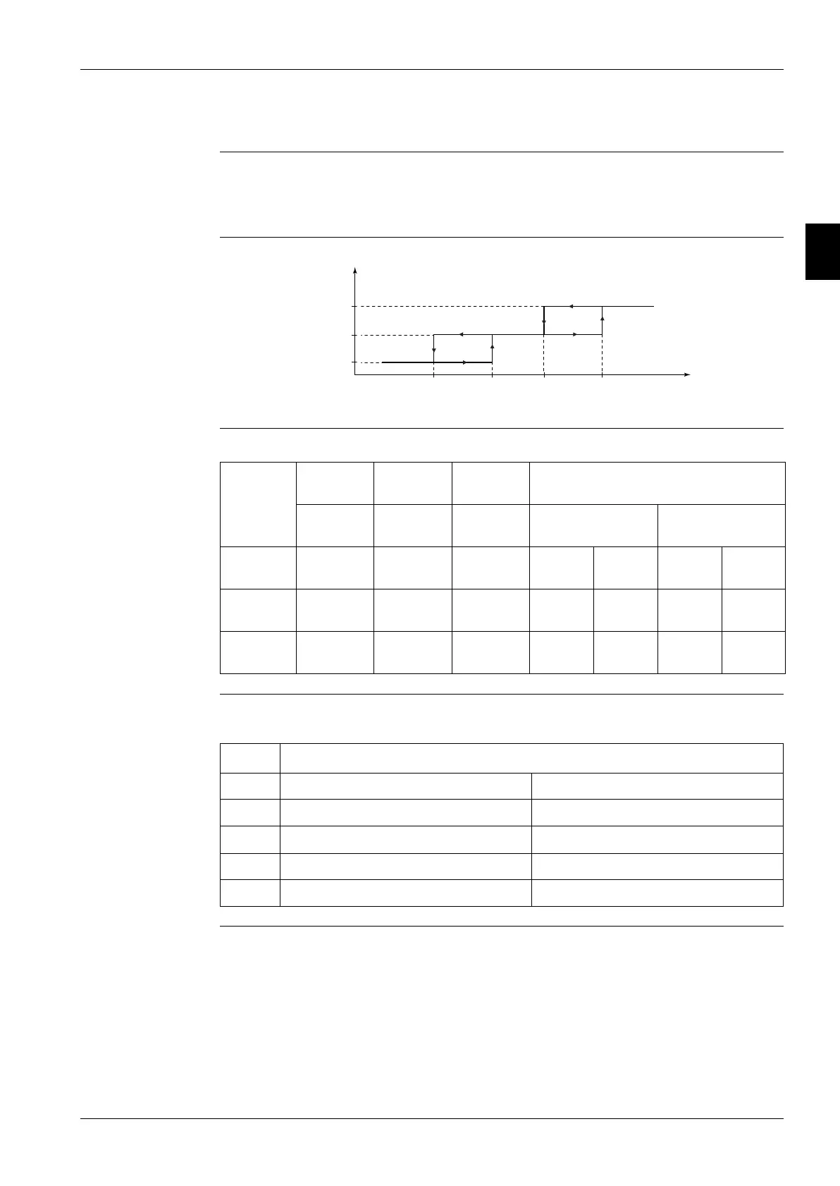
The illustration below shows the fan management in cooling mode.
Fan relay
management in
cooling mode
The table below describes the fan relay management in cooling mode.
Fan motor
operation
The operation of the fan motors depends on the ambient temperature. The table below contains the
fan settings for different ambient temperatures.
Selection of fan
setting
Fan setting 1 or Fan setting 2 is selected by dipswitch S2A number 2:
■ OFF = fan setting 1
■ ON = fan setting 2
Fanstep 3
Fanstep 1
Fanstep 2
T1 T2 T3 T4
T
ambient
Fan
relay 1
Fan
relay 2
Fan
relay 3
Result
RY4/RY24 RY5/RY25 RY12 For units with 2 cir-
cuits and fans
Fanstep 1 Open Closed Open M11F:
medium
M12F:
OFF
M21F:
medium
M22F:
OFF
Fanstep 2 Closed Open Open M11F:
high
M12F:
OFF
M21F:
high
M22F:
OFF
Fanstep 3 Closed Open Closed M11F:
high
M12F:
high
M21F:
high
M22F:
high
T
ambient
Fan setting 1 (5HP, 8HP, 16HP) Fan setting 2 (10HP, 12HP, 20HP, 24HP)
T1 5°C -4°C
T2 7°C -2°C
T3 17°C 15°C
T4 19°C 17°C
 Loading...